Multi-station drilling machine

A drilling machine, multi-station technology, used in boring/drilling, drilling/drilling equipment, metal processing machinery parts, etc., can solve problems such as unsuitable crystal drilling operations

Inactive Publication Date: 2014-02-12
杨贵庭
View PDF8 Cites 23 Cited by
  • Summary
  • Abstract
  • Description
  • Claims
  • Application Information

AI Technical Summary

Problems solved by technology

"The problem that this invention exists is: this invention is suitable for the drilling operation of large-scale workpiece, and the wheel hub to be processed is fixed on the machine and clamped on the workbench, the wheel hub to be processed does not need to be turned over during the drilling operation, And if the number of holes to be drilled on the wheel hub to be processed exceeds two, after the two holes are drilled, it is necessary to adjust the position of the wheel hub to be processed and then re-clamp, so the disclosed technical scheme of the invention is not suitable. Drilling operations for crystals require

Method used


Image

  • Multi-station drilling machine
  • Multi-station drilling machine
  • Multi-station drilling machine

Examples


Embodiment 1

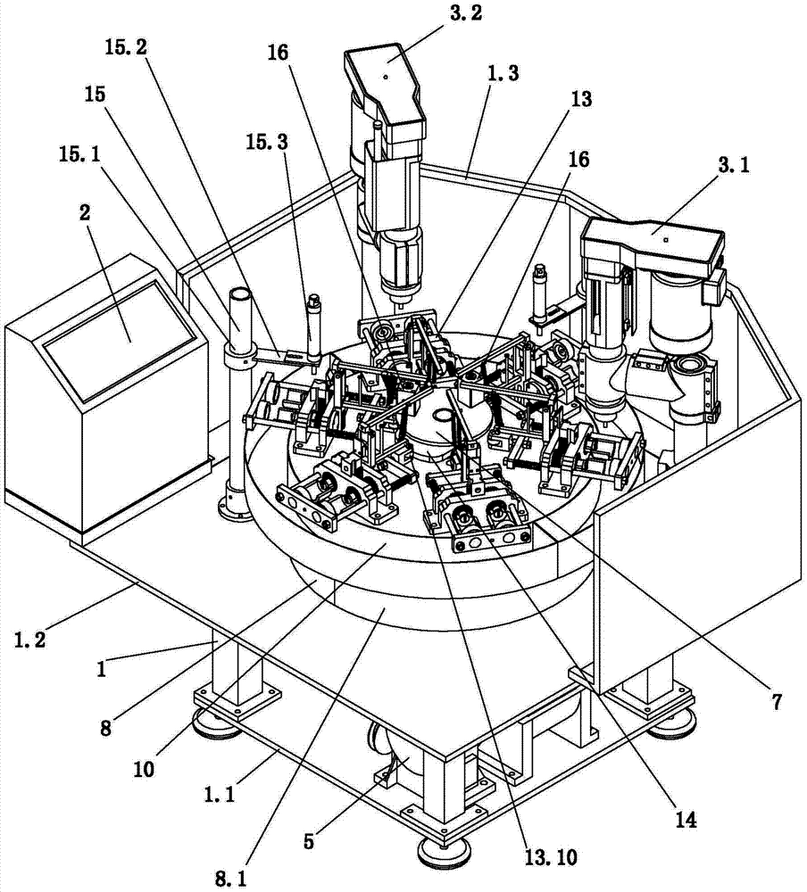
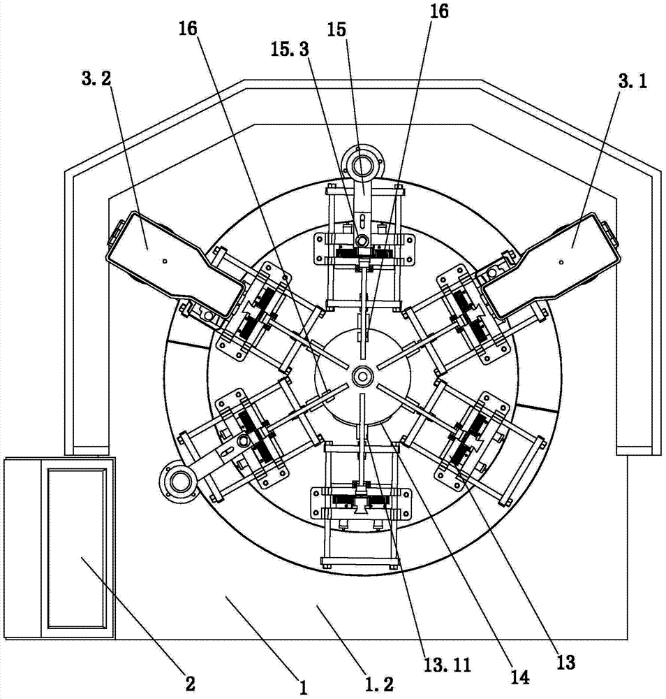
[0047] In the embodiment, assuming that the charging station is located at the forefront of the multi-station drilling machine, the first and second drilling mechanisms are respectively located at the oblique rear on the right side and obliquely rear on the left side of the charging station, and each 120 to the charging station 0 Angular distribution, the turntable rotates intermittently counterclockwise.

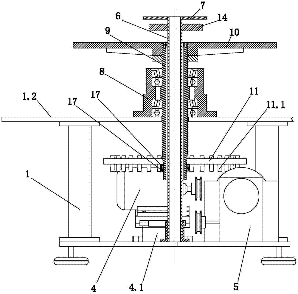
[0048] Such as figure 1 , figure 2 with image 3 Shown, the present invention comprises electric control box 2, frame 1, power mechanism and two into 120 0 The first and second drilling mechanisms 3.1, 3.2 arranged on the frame in angular distribution, and the air source system not shown in the figure. The air source system includes a connecting pipeline and a solenoid valve installed on the pipeline. The middle part of the upper deck 1.2 of the frame 1 is provided with a through hole, and the lower end of the vertical shaft 6 is fixedly connected with the frame 1 aft...

Embodiment 2

[0074] Such as figure 1 , image 3 with Figure 7 As shown, the difference between embodiment two and embodiment one is that embodiment two is also provided with two rack hitting cylinder mechanisms 15, and the rack hitting cylinder mechanism 15 includes hitting cylinder mounting columns 15.1, outer ends and The hitting cylinder installation rod 15.2 fixedly connected to the upper end of the hitting cylinder mounting column 15.1 and the hitting cylinder 15.3 fixed on the inner end of the hitting cylinder mounting rod 15.2; On the extension line between the center and the piston center of the two push cylinders 16, the lower end of the hitting cylinder mounting column 15.1 is firmly connected with the upper table 1.2, and the lower end 15.3.1 of the piston rod of the hitting cylinder 15.3 is located in the corresponding clamping Above the rear end of the rack 13.3 of the mechanism 13. As preferably, the hitting cylinder mounting rod 15.2 is adjustable to the hitting cylinder...


PUM


Abstract

The invention relates to a multi-station drilling machine for crystal drilling operation. The multi-station drilling machine comprises an electric cabinet, a machine frame, a power mechanism and two drilling mechanisms, wherein the lower end of a vertical shaft passes through a through hole in the upper layer table facet of the machine frame and is fixedly connected with the machine frame; a mounting disc and a charging cam are fixedly arranged at the upper end of the vertical shaft; a bearing pedestal is arranged at the through hole position; a rotary pipe is arranged on the vertical shaft in a sleeving manner and is rotationally connected with the bearing pedestal; the upper end of the rotary pipe stretches out of the bearing pedestal and is fixedly connected with a rotary plate; the lower end of the rotary pipe stretches below the upper layer table facet and is in transmission connection with the output shaft of the power mechanism; six clamping mechanisms are circumferentially and uniformly distributed at the circumferential edge of the upper surface of the rotary plate; each clamping mechanism is provided with a crystal clamping mechanism and a charging mechanism which works in combination with the charging cam; one crystal clamping mechanism between the two drilling mechanisms enters the lower part of the second drilling mechanism after the upper end of the crystal, relative to the first drilling mechanism, is turned over by 180 degrees to become the lower end of the crystal, and then the crystal clamping mechanism is turned back by 180 degrees to return a charging state when being positioned behind the second drilling mechanism and in front of a charging station.

Description

technical field [0001] The invention relates to crystal processing equipment, in particular to a multi-station drilling machine for drilling holes on crystals. [0002] Background technique [0003] Existing drilling machines that carry out drilling operations to crystals all adopt common industrial bench drills to drill holes, and the procedures of drilling operations are not concentrated, and the same drilling operations require many equipment and operators. During the drilling operation, the crystal workpiece is fixed on the fixture of the workbench, and the workpiece must be turned around during the drilling operation to complete the entire drilling operation. And the cutting tool of drilling operation will be manually clamped by the worker, and the tool clamping is inconvenient. In addition, frequent manual clamping is required when workpieces are loaded, and only one workpiece can be loaded each time. The workpiece clamping is time-consuming and laborious. In additi...

Claims


Application Information

Patent Timeline
IPC IPC(8): B28D5/02B28D7/04B23B47/30B23B39/10B23Q3/06
Inventor 杨贵庭刘根平
Owner 杨贵庭
Why Eureka
Try Eureka