Method for detecting large-caliber large-relative-aperture parabolic reflector surface shape error

A technology of relative aperture and mirror surface, applied in the field of optical testing, can solve the problems of high price, strict requirements for assembly and adjustment accuracy, and difficulty in manufacturing high-precision flat mirrors, to reduce hardware requirements, improve lateral resolution, reduce The effect of precision requirements

Active Publication Date: 2014-02-12
XIAN TECHNOLOGICAL UNIV
View PDF10 Cites 21 Cited by
  • Summary
  • Abstract
  • Description
  • Claims
  • Application Information

AI Technical Summary

Problems solved by technology

The self-collimation method uses a pair of conjugate aberration-free points (geometric focus and infinity) on the paraboloid. When the point light source is precisely located on the geometric focus, a high-precision flat mirror with the same diameter as the measured parabolic mirror can be used. Realize conjugation, however, it is difficult and expensive to manufacture high-precision flat mirrors required for large-diameter parabolic mirrors, and it is even more difficult to achieve self-collimation for super-large-diameter parabolic mirrors, and it is necessary to choose a larger relative aperture parabolic mirror The relative aperture transmission standard mirror, with the increase of the relative aperture, the transmission standard mirror can no longer satisfy the detection of the large relative aperture parabolic mirror; the compensation mirror zero position inspection method is to convert the plane wavefront or spherical wavefront to The parabolic wavefront coincides with the theoretical shape of the tested parabolic mirror, and its biggest advantage is that the diameter of the compensation mirror is much smaller than t

Method used


Image

  • Method for detecting large-caliber large-relative-aperture parabolic reflector surface shape error
  • Method for detecting large-caliber large-relative-aperture parabolic reflector surface shape error
  • Method for detecting large-caliber large-relative-aperture parabolic reflector surface shape error

Examples


Embodiment Construction

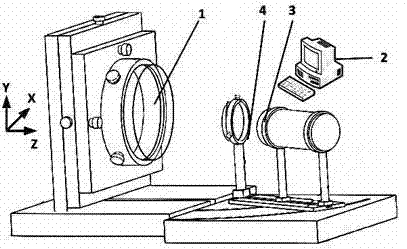
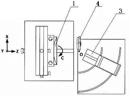
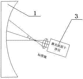
[0030] see figure 1 and figure 2 , the detection device used in the inventive method comprises laser wavefront interferometer 3, measured parabolic reflector 1, standard plane reflector 4 and main control computer 2, laser wavefront interferometer 3, measured parabolic reflector 1, standard The plane mirrors 4 are all operated by their respective adjustment mechanisms.

[0031] The specific device is a known structural combination;

[0032] The movement of the laser wavefront interferometer is controlled by its adjustment mechanism. The center of rotation of the adjustment mechanism is O, and the focus of the laser wavefront interferometer 3 coincides with its rotation center O through the action of the adjustment mechanism; The wave surface interferometer 3 rotates at a certain angle around its focal point (ie, the center of rotation O).

[0033] The adjustment mechanism of the parabolic mirror 1 under test includes an X-axis motion adjustment platform, a Y-axis motio...


PUM


Abstract

The invention relates to a method for detecting a large-caliber large-relative-aperture parabolic reflector surface shape error. An existing method is high in cost and low in accuracy and efficiency. The method includes the steps of selecting a transmission standard lens, adjusting the position of a laser wave surface interferometer, adjusting a focus of a tested parabolic reflector to be coincided with a focus of the laser wave surface interferometer, adjusting the optical axis of the tested parabolic reflector to enable the optical axis of the tested parabolic reflector and the optical axis of the laser wave surface interferometer to be coaxial, adjusting a standard plane reflector, rotating the laser wave surface interferometer to enable the laser wave surface interferometer to be aligned with a first annular sub-aperture A, and repeating the sixth step and the seventh step according to a sub-aperture division scheme. The method for detecting the large-caliber large-relative-aperture parabolic reflector surface shape error is low in cost and high in accuracy and efficiency.

Description

technical field [0001] The invention belongs to the technical field of optical testing, and mainly relates to a method for detecting the surface shape error of a rotationally symmetrical large-aperture and large-relative-aperture parabolic mirror. technical background [0002] The optical system with a parabolic mirror as the main mirror has been more and more widely used in high-tech fields such as astronomical optics, space optics, and military affairs. In order to increase the light-gathering ability and peak light intensity of the optical system, the outstanding features of the optical system are Large caliber and large relative aperture. The manufacture of large-diameter and large-relative-aperture parabolic mirrors requires corresponding inspection technologies. However, there are still many challenges in the high-precision inspection of large-diameter and large-relative-aperture parabolic mirrors. [0003] In the polishing stage of the paraboloid, the usual quantitat...

Claims


Application Information

Patent Timeline
IPC IPC(8): G01B11/24
Inventor 刘丙才王红军王春慧朱学亮田爱玲潘永强杨皓聿鲍佳男
Owner XIAN TECHNOLOGICAL UNIV
Why Eureka
Try Eureka