

Method for chamfering wafer, apparatus for chamfering wafer, and jig for adjusting angle of grindstone
A processing method and a processing device technology, which are applied in the field of wafer chamfering processing and devices, and tools for adjusting the angle of abrasive tools, can solve problems such as partial wear of abrasive tools, shortened contact length, and time-consuming chamfering processing, and achieve Effects of increased throughput and extended contact length
- Summary
- Abstract
- Description
- Claims
- Application Information
AI Technical Summary
Problems solved by technology
Method used
Image

Examples
Embodiment Construction
[0086] [Wafer chamfering method]
[0087] Hereinafter, a method of chamfering a wafer according to an embodiment of the present invention will be described.
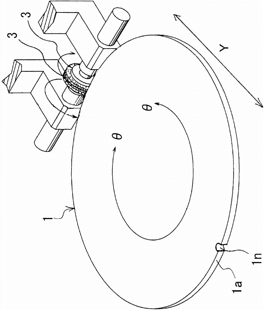
[0088] Wafer chamfering processing method as an example such as Figure 1~6 As shown, the outer peripheral surfaces of the disc-shaped grooveless grinders 3 and 3 formed in the shape of a disc are brought into contact with the wafer 1, and two disc-shaped grooveless grinders 3 and 3 are simultaneously brought into contact with one wafer 1. For chamfering.
[0089] In the embodiment of the present invention, the wafer 1 is placed on the turntable 2a provided on the workpiece mounting table 2 (refer to Figure 4 ), and using two disk-shaped grooveless grinders 3, 3, the wafer 1 rotating together with the turntable 2a is chamfered simultaneously.
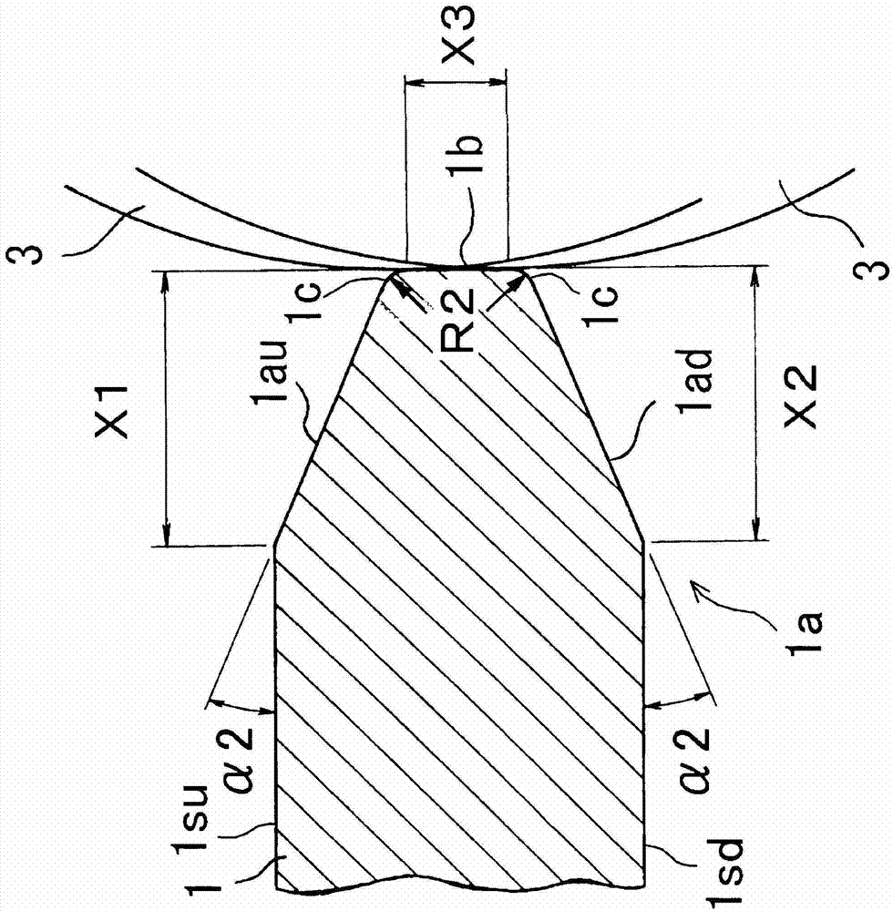
[0090] 2 disc-shaped grooveless grinding tools 3, 3 are close to the same part of the peripheral end 1b, and the sides facing each other are arranged close to each other, and ...
PUM
 Abstract
Description
Claims
Application Information