Method for determining position of root of blast furnace cohesive zone through multi-source information fusion

A technology of multi-source information fusion and reflow zone, which is applied in the field of iron and steel smelting, can solve the problems of backward detection technology of reflow zone position and shape, difficulty in giving accurate results, etc., and achieve low equipment investment and strong operability , the effect of high detection accuracy

Active Publication Date: 2014-02-19
CENT SOUTH UNIV
View PDF4 Cites 26 Cited by
  • Summary
  • Abstract
  • Description
  • Claims
  • Application Information

AI Technical Summary

Problems solved by technology

Due to limitations in capital and technology, few domestic blast furnaces are equipped with detection devices, and the detection technology for the position and shape of the reflow zone is still very backward.
At present, blast furnace operators mainly estimate the approximate position of the root of the reflow zone by referring to measurement data such as blast furnace gas composition, furnace top pressure, furnace top temperature, furnace throat cross temperature measurement, stave temperature, and molten iron temperature, combined with operating experience, which is difficult to give exact result

Method used


Image

  • Method for determining position of root of blast furnace cohesive zone through multi-source information fusion
  • Method for determining position of root of blast furnace cohesive zone through multi-source information fusion
  • Method for determining position of root of blast furnace cohesive zone through multi-source information fusion

Examples


Embodiment 1

[0055] The blast furnace used is a 2500m steel plant 3 level blast furnace.

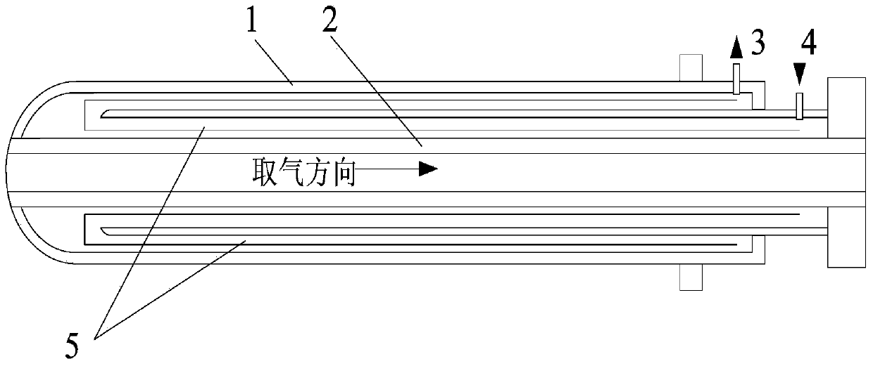
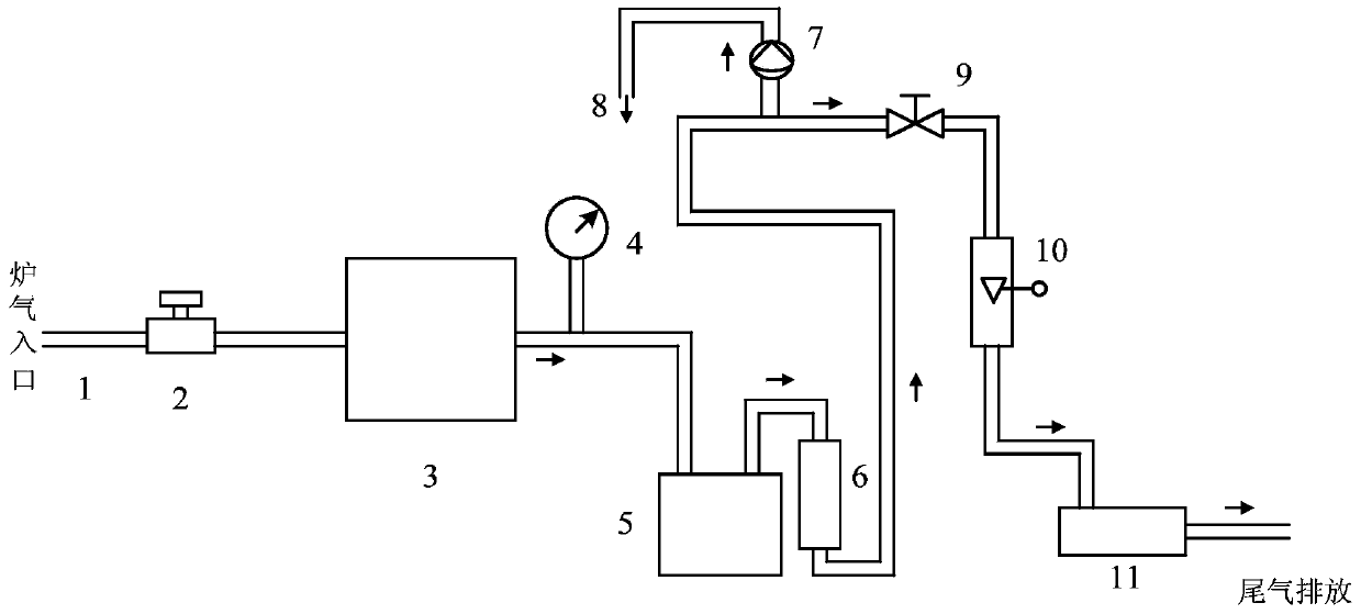
[0056] A Take blast furnace gas along different heights of the blast furnace shaft, measure and draw the distribution curve of gas utilization along the height direction, and use numerical calculation methods to obtain η co The elevation position of zero (the flow chart of blast furnace gas composition extraction and analysis is shown in figure 2 , the blast furnace gas is taken out from the sampling probe 1, and flows through the high-pressure anti-corrosion solenoid valve 2, dust filter 3, alarm pressure gauge 4, gas-water separator 5, dryer 6, explosion-proof air pump 7, residual gas recovery 8, regulation valve 9, gas flow meter 10, gas chromatograph analyzer 11 for extraction and analysis);

[0057] A1 The blast furnace is equipped with static pressure holes (total 12 points) in the four directions of east, south, west and north on the three floors with the height of the furnace body (relativ...


PUM


Abstract

The invention provides a method for determining the position of the root of a blast furnace cohesive zone through multi-source information fusion. The method specifically includes the following steps that A gas is taken along the different heights of a blast furnace body, a distribution curve, along the height, of gas utilization rates is drawn, and when the gas utilization rate is zero, the elevation position of the gas utilization rate is obtained through a numerical computation method; B a distribution relation model, in the height direction, of the temperature of the hot surface of a furnace wall of the blast furnace is built, and the area where the temperature of a cooling wall changes obviously is obtained; C the soft melting temperature of a furnace burden corresponding to a furnace burden grade during measurement of A and B is analyzed and determined according to the soft melting temperatures of different furnace burden grades; D the distribution relation model, in the height direction, of the temperature of the hot surface of the furnace wall of the blast furnace is used as main-source information and conclusions of A and C are used as auxiliary information for computing the position of the root of the cohesive zone. By means of the method, according to detectable data, a temperature field distribution model of the hot surface of the furnace wall of the blast furnace, the elevation position where the CO utilization rate is zero and the soft melting temperature of the furnace burden of the blast furnace during data measurement are obtained, the position of the root of the blast furnace cohesive zone is worked out, and the method has the advantages of being small in equipment investment, high in detection precision and the like.

Description

technical field [0001] The invention relates to the field of iron and steel smelting, in particular to a method for determining the position of the root of a blast furnace reflow zone through multi-source information fusion. Background technique [0002] Blast furnace smelting, as the upstream process of steel production process, is the main source of CO in steel production. 2 The main discharge process and the link with the largest energy consumption. The reflow zone in the blast furnace not only dominates the gas flow distribution, directly affects the utilization of blast furnace gas, but also has a great influence on the heat exchange, reduction process and air permeability in the furnace. Blast furnace anatomy and experimental simulation have confirmed its existence. The reflow property of charge and blast furnace operating system are the main factors affecting the position and shape of the reflow zone. The refractory zone model is an intuitive reflection and importan...

Claims


Application Information

Patent Timeline
Patent Type & Authority Applications(China)
IPC IPC(8): G06F17/50C21B5/00
Inventor 桂卫华杨贵军蒋朝辉阳春华郑源斌
Owner CENT SOUTH UNIV
Why Eureka
Try Eureka