CMOS asynchronous time domain image sensor capable of achieving real-time time stamp
- Summary
- Abstract
- Description
- Claims
- Application Information
AI Technical Summary
Problems solved by technology
Method used
Image

Examples
Embodiment Construction
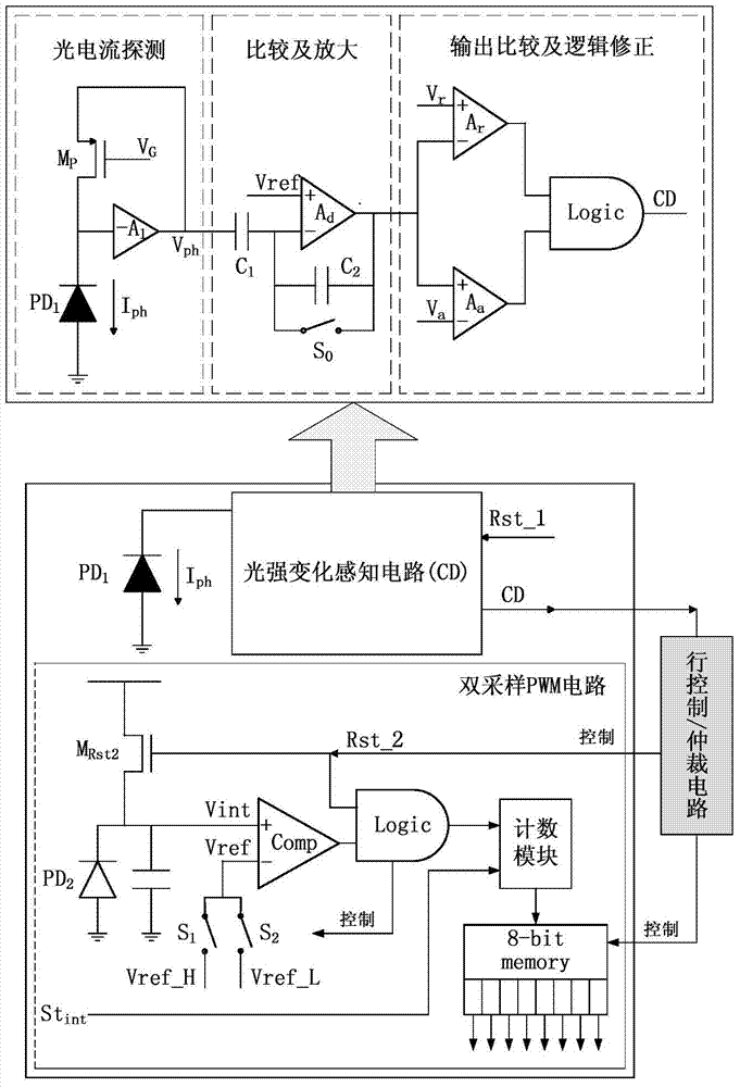
[0022] The sensor of the present invention adopts a 128*128 pixel array, and the structure is as follows Figure 4 As shown, it consists of a row / column reset control circuit, a row arbitration circuit, a row time stamp circuit and a row / column address encoding circuit.
[0023] (1) Row / column reset control circuit. The column reset control circuit (x_reset control) controls the reset of each pixel CD circuit, and the control signal x_Rst is shared by the column. The row reset control circuit (y_reset control) controls the reset of the double sampling PWM circuit of each pixel, and the control signal y_Rst is shared by row. The advantage of setting and resetting the CD circuit and the double-sampling PWM circuit separately is that the double-sampling PWM circuit can be directly controlled when the global shooting mode or the snapshot mode is in operation, and the CD circuit is in a standby state.
[0024] (2) Row arbitration circuit (y_arbiter). When the light changes, the ...
PUM
 Abstract
Description
Claims
Application Information
 - Generate Ideas
- Intellectual Property
- Life Sciences
- Materials
- Tech Scout
- Unparalleled Data Quality
- Higher Quality Content
- 60% Fewer Hallucinations
Browse by: Latest US Patents, China's latest patents, Technical Efficacy Thesaurus, Application Domain, Technology Topic, Popular Technical Reports.
© 2025 PatSnap. All rights reserved.Legal|Privacy policy|Modern Slavery Act Transparency Statement|Sitemap|About US| Contact US: help@patsnap.com