Optical switching method capable of using electronic control quadratic electro-optical effect for deflecting incident light

A secondary electro-optic and incident light technology, applied in the optical field, can solve problems such as difficult practical application, and achieve the effects of low cost, broad application prospects and small size

Inactive Publication Date: 2014-02-26
HARBIN INST OF TECH
View PDF4 Cites 18 Cited by
  • Summary
  • Abstract
  • Description
  • Claims
  • Application Information

AI Technical Summary

Problems solved by technology

However, since there is no good way to solve the erasure problem of

Method used


Image

  • Optical switching method capable of using electronic control quadratic electro-optical effect for deflecting incident light
  • Optical switching method capable of using electronic control quadratic electro-optical effect for deflecting incident light

Examples


specific Embodiment approach 1

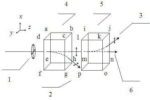
[0031] Specific implementation mode one: combine figure 1 In this embodiment, an optical switch method for realizing deflection of incident light by using the electronically controlled secondary electro-optic effect, the specific process is as follows:

[0032] Step 1. Cut two pieces of potassium tantalum niobate crystals grown by the pulling method with a Curie temperature near room temperature (temperature range of 10-30 degrees Celsius) along the crystal axes of [100], [010] and [001] Cuboid, then polished on all sides. The temperature of the potassium tantalum niobate crystal should be controlled within 20 degrees higher than its Curie temperature.

[0033] Step 2. Correspond the [100], [010] and [001] crystal axes of the two crystals to the x, y, and z axes of the Cartesian coordinate system, and place them in sequence along the z axis. At this time, the z axis is the entire optical system The optical symmetry axes of the two crystals in the middle are the first...

specific Embodiment approach 2

[0037] Specific embodiment two: this embodiment is a further description of specific embodiment one, the size of the first crystal 4 used in step one is 5.00 (ab) × 2.00 (ae) × 1.50 (ad) cubic millimeters, the second crystal 4 The dimensions of the crystal 5 are 5.00(ij)×2.00(il)×1.50(im) cubic millimeters.

specific Embodiment approach 3

[0038] Embodiment 3: This embodiment is a further description of Embodiment 1. The Curie temperature of the potassium tantalum niobate crystal used in step 1 is 20 degrees Celsius, and the crystal temperature is 22 degrees Celsius.


PUM

PropertyMeasurementUnit
Curie temperatureaaaaaaaaaa

Abstract

The invention provides an optical switching method capable of using the electronic control quadratic electro-optical effect for deflecting incident light, belongs to the technical field of optics, and aims to solve the problem in the existing optical switching technology that a broadband range and quick responses cannot be realized. The optical switching method specifically comprises the following steps: a quadratic electro-optical effect potassium tantalate niobate crystal is used; when laser radiation is needed, an external electric field is not applied to the crystal, and lasers directly penetrate through the crystal; when laser radiation is not needed, the external electric field is applied to the crystal in the two directions perpendicular to the incident lasers, and the quadratic electro-optical effect is used for making polarized components in the incident lasers be polarized sequentially after the polarized components pass through the crystal, wherein the polarization direction of the polarized components is parallel to the direction of the externally applied electric field; finally, the polarized components deviate from the original propagation direction, and the purpose of switching on and off is achieved. An optical switch manufactured by the adoption of the optical switching method has the advantages of being small in size, low in cost, easy to process, and high in response speed (at a nanosecond level), so that the application prospect of the optical switch is quite broad.

Description

technical field [0001] The invention belongs to the field of optical technology, and relates to an optical switch method for realizing deflection of incident light by using electronically controlled secondary electro-optic effect. Background technique [0002] Optical switch is the core technology of optical information transmission and information processing. At present, optical switches mainly include mechanical optical switches, thermo-optical switches, liquid crystal optical switches, bubble optical switches, acousto-optic optical switches and electronically controlled holographic optical switches. [0003] The mechanical optical switch is mainly composed of a moving optical fiber, a moving sleeve, a moving collimator, a moving mirror, a moving prism and a moving coupler. After years of development, the mechanical optical switch has been relatively mature, and its advantages are low insertion loss (≤2dB), high isolation (>45dB), and not affected by the polarization ...

Claims


Application Information

Patent Timeline
IPC IPC(8): G02F1/03
Inventor 宫德维周忠祥
Owner HARBIN INST OF TECH
Why Eureka
Try Eureka