Sensing head of fluorescent fiber sensor and preparation method of sensing head

A fluorescent optical fiber and sensor technology, applied in the field of sensor heads, can solve problems such as large sample volume, and achieve the effects of improving light stability, sensitivity, sensitivity and sensor stability.

Inactive Publication Date: 2014-03-05
SHANGHAI UNIVERSITY OF ELECTRIC POWER
View PDF3 Cites 10 Cited by
  • Summary
  • Abstract
  • Description
  • Claims
  • Application Information

AI Technical Summary

Problems solved by technology

[0005] The purpose of the present invention is to solve the traditional optical fiber evanescent wave fluorescence sensor to remove complex processes such as coating and cladding in order to improve the sensitivity and the tr

Method used


Image

  • Sensing head of fluorescent fiber sensor and preparation method of sensing head

Examples


Embodiment 1

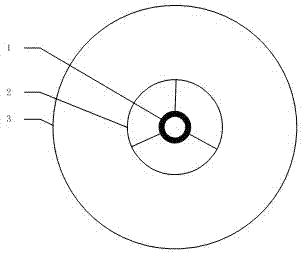
[0021] A sensing head of a fluorescent optical fiber sensor, its structure schematic diagram is as follows figure 1 As shown, it is a wheel-shaped microstructure, including a core 1, a cladding 3 and an air hole 2, the core 1 and the cladding 3 are connected by 3 tie bars, and the inner wall of the air hole 2 is coated with There is a layer of nano-gold / methyl methacrylate with a thickness of 20nm.

[0022] The preparation method of the sensing head of the above-mentioned a kind of fluorescent optical fiber sensor specifically comprises the following steps:

[0023] (1) First, pour 500ul of 0.1 mM nano-gold phosphate buffer solution into 2ml of dichloromethane solvent, then pour 300ul of dodecyl mercaptan into the above solution, and stir for 1min with a magnetic stirrer , suck out the nano-gold with a straw, place it in an oven at 75°C for 6 hours to evaporate the solvent, then pour 1ml of dichloromethane into the evaporated gold nano-gold, the solution turns red, indicating...


PUM

PropertyMeasurementUnit
Thicknessaaaaaaaaaa
Diameteraaaaaaaaaa
Lengthaaaaaaaaaa

Abstract

The invention relates to a sensing head of a fluorescent fiber sensor. The sensing head of the fluorescent fiber sensor is of a wheel-shaped microstructure and comprises a fiber core, a coating layer and an air hole, wherein the fiber core and the coating layer are connected through tiepieces; and the inner wall of the air hole is coated with one layer of nanogold/methyl methacrylate with the thickness of 20 nm. A preparation method of the sensing head of the fluorescent fiber sensor comprises the following steps: preparing the nanogold/methyl methacrylate; coating the nanogold/methyl methacrylate on the inner wall of the air hole of the wheel-shaped microstructure fiber; and after coating is finished, roasting for 6 hours by controlling the temperature to be 50 DEG C so as to volatilize a dichloromethane solvent to obtain the sensing head of the fluorescent fiber sensor. Compared with the like products, the sensing head of the fluorescent fiber sensor has the advantages that the lower limit and the sensitivity of fluorescent detection of the sensing head can be increased by 20 times; the required sample amount is at nL amount order.

Description

technical field [0001] The invention relates to a sensing head, in particular to a sensing head of a fluorescent optical fiber sensor and a preparation method thereof. Background technique [0002] The metal surface enhanced fluorescence effect refers to the effect that the strong local surface plasmon resonance of metal nanoparticles greatly enhances the electromagnetic field around the metal particles, thereby changing the free space conditions of the surrounding phosphors, and enhancing the fluorescence of the phosphors. It was first discovered by Drexhage in the 1970s. This effect has the advantages of increasing the fluorescence quantum yield of the phosphor, increasing the Forster distance, and improving the stability of the fluorescence. In recent years, as a new generation of biological detection, labeling and development of fluorescent chemical sensors, it has become a research hotspot. [0003] Optical fiber sensors have the advantages of high sensitivity, small ...

Claims


Application Information

Patent Timeline
IPC IPC(8): G01N21/64
Inventor 初凤红
Owner SHANGHAI UNIVERSITY OF ELECTRIC POWER
Why Eureka
Try Eureka