High-power signal emission source and monitoring method for dynamic monitoring of remaining oil in oilfield by potentiometric method
A dynamic monitoring and high-power technology, which is applied in construction and other directions, can solve the problems of low transmission power of the signal transmission source, cannot be fully satisfied, and has no economic benefits, and achieves the effects of light weight, improved field test efficiency, and low cost
- Summary
- Abstract
- Description
- Claims
- Application Information
AI Technical Summary
Problems solved by technology
Method used
Image

Examples
Embodiment 1
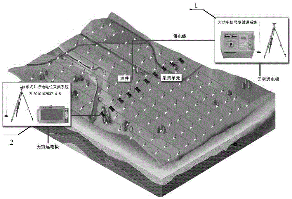
[0037] a. According to figure 1 The distributed parallel potential acquisition system 2 and the high-power signal emission source system 1 are arranged as shown, and are connected through their respective trigger ports by cables to realize signal emission and data acquisition in the synchronous mode of wire control.
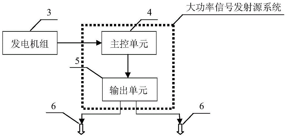
[0038] b. Connect the generator set 3 with the main control unit 4 in the high-power signal transmitting system 2 .
[0039] c. Determine the working parameters of the high-power signal transmitting system 2 through experiments, including parameters such as square wave frequency, cycle number, and supply current, and import the working parameters into the U disk through the host computer of the distributed parallel potential acquisition system 2.
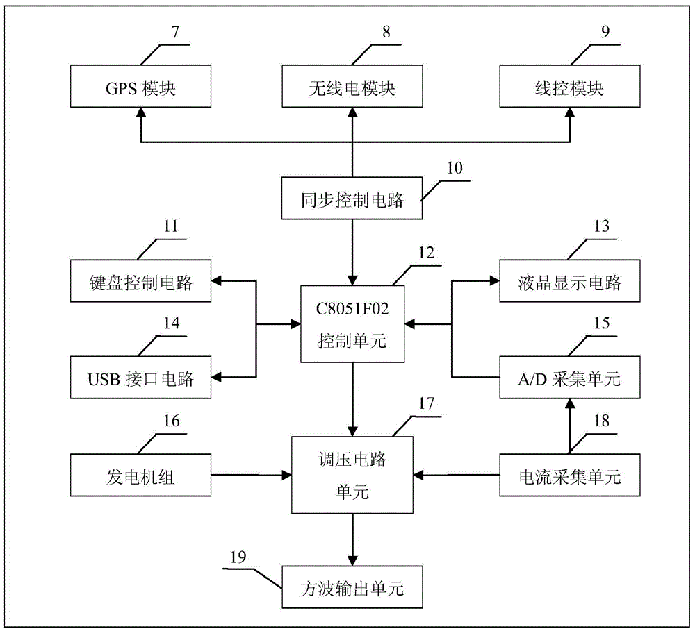
[0040] d. Insert the U disk loaded with the working parameters into the USB port of the main control unit 4 of the high-power signal transmitting system 1, and the main control unit 4 automatically imports the working ...
Embodiment 2
[0045] a. According to figure 1 The distributed parallel potential measurement system 1 and the high-power signal transmission system 2 are arranged as shown, and high-gain radio antennas are connected to their respective radio antenna ports to realize signal transmission and data collection in radio synchronization mode.
[0046] b. Connect the generator set 3 with the main control unit 4 in the high-power signal transmitting system 2 .
[0047] c. Determine the power supply current parameters of the high-power signal transmitting system 2 through experiments.
[0048] d. Use the keyboard in the main control unit 4 to select the radio control trigger mode, and start the Run key of the main control unit 4 to enter the running mode. At this time, the main control unit is under the control of the distributed parallel potential acquisition system 2 host.
[0049] d. The distributed parallel potential acquisition system 2 performs radio communication verification with the main co...
Embodiment 3
[0051] a. According to figure 1 The distributed parallel potential collection system 2 and the high-power signal transmission system 1 are arranged as shown, and GPS antennas are connected to the respective GPS ports to realize signal transmission and data collection in the GPS timing synchronization mode.
[0052] b. Connect the generator set 3 with the main control unit 4 in the high-power signal transmitting system 1 .
[0053] c. Determine the working parameters of the high-power signal transmitter through experiments, including parameters such as the frequency of the square wave, the number of cycles, and the power supply current, and import the working parameters into the U disk through the host computer of the distributed parallel potential acquisition system 2.
[0054] d. Insert the U disk loaded with the working parameters of the transmitter into the USB port of the main control unit 4, and the main control unit 4 will automatically import the parameters into the mai...
PUM
 Abstract
Description
Claims
Application Information
 - R&D
- Intellectual Property
- Life Sciences
- Materials
- Tech Scout
- Unparalleled Data Quality
- Higher Quality Content
- 60% Fewer Hallucinations
Browse by: Latest US Patents, China's latest patents, Technical Efficacy Thesaurus, Application Domain, Technology Topic, Popular Technical Reports.
© 2025 PatSnap. All rights reserved.Legal|Privacy policy|Modern Slavery Act Transparency Statement|Sitemap|About US| Contact US: help@patsnap.com