Low-profile adjustable tri-band antenna

A low-profile, antenna technology, applied in the field of electronics, can solve the problems of large antenna influence, less satellite antenna, high cost, and achieve the effect of reducing the number of PIN switches, reducing the size of the antenna, and broadening the impedance bandwidth

Active Publication Date: 2014-03-12
XIDIAN UNIV
View PDF4 Cites 19 Cited by
  • Summary
  • Abstract
  • Description
  • Claims
  • Application Information

AI Technical Summary

Problems solved by technology

[0004] To sum up, currently reconfigurable antennas are facing three problems. 1. Adjustable frequencies are mainly concentrated in low-frequency bands such as WLAN, and there are few satellite antennas suitable for high-frequency X, Ku-band and even Ka-band
2. Switch selection, the use of PIN switches is more mature, but the design of the DC bias line has a greater impact on the antenna when the PIN switch is loaded on the antenna. MEMS switches are easy to use, but the development of MEMS switch preparation methods is not mature enough. At the same time The cost is high, and there are problems in engineering use
3. Under the condition of low profile, it cannot meet the requirements of high antenna gain

Method used


Image

  • Low-profile adjustable tri-band antenna
  • Low-profile adjustable tri-band antenna
  • Low-profile adjustable tri-band antenna

Examples


Embodiment 1

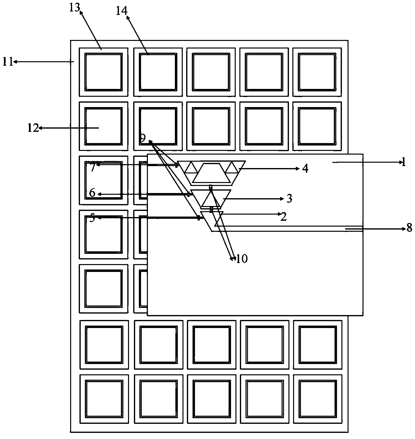
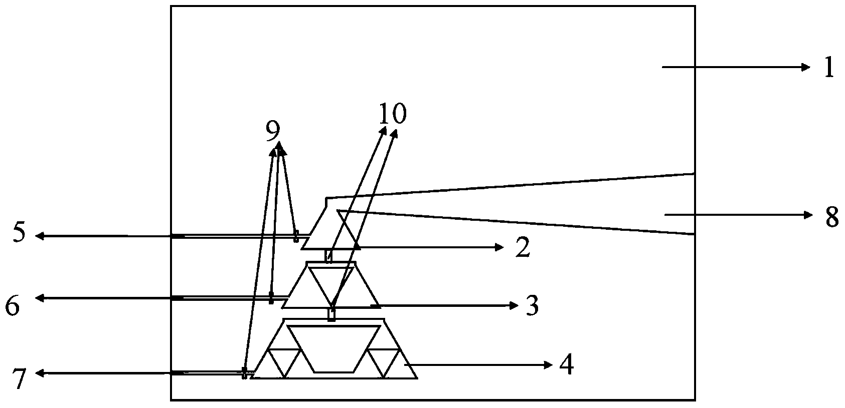
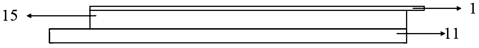
[0036] Aiming at the shortcomings of the existing reconfigurable antenna, such as low operating frequency, low gain, high cross-section, and at the same time, the loading switch has a great influence on the radiation characteristics of the antenna, which cannot meet the needs of satellite communication, etc., the present invention has carried out innovation and research. The low Profile tri-band tunable antenna, see figure 1 , including: a first dielectric substrate 1, a first-order radiation unit 2, a second-order radiation unit 3, a third-order radiation unit 4, a dual-feed microstrip line 8, a second dielectric substrate 11, and the second dielectric substrate 11 is printed Periodic EBG unit 12, EBG unit 12 includes a square patch 13 printed on the upper layer of the second dielectric substrate 11 and etched with a square ring slit 14 and a metal floor printed on the lower layer of the second dielectric substrate 11, in other words, the second dielectric substrate 11 The lo...

Embodiment 2

[0041] The composition and structure of the low-profile three-frequency adjustable antenna are the same as those in Embodiment 1. In this embodiment, the radiation patch in the radiation unit printed on the first dielectric substrate is a triangle, and the side length a1 of the triangle of the radiation patch of the first-order radiation unit is 1 mm. The side length a2 of the radiation patch triangle of the first-order radiation unit is 1 mm, the side length a3 of the triangle radiation patch of the third-order radiation unit is 3 mm, the thickness of the foam board between the first dielectric substrate and the second dielectric substrate is 1 mm, and on the second dielectric substrate The EBG unit patch etching slit width is 1mm, and the periodically arranged EBG unit patches produce reflection phase characteristics of X-band and Ku-band. In this example, the inductance value connected to the DC bias line on the first dielectric substrate is 0.1 μH, the dielectric constant o...

Embodiment 3

[0043] The composition and structure of the low-profile three-frequency adjustable antenna are the same as those in Embodiment 1-2. In this embodiment, the radiation patch of each order of radiation unit printed on the first dielectric substrate is a triangle, and the side length of the triangle of the radiation patch of the first-order radiation unit is a1 is 3 mm, the side length a2 of the triangle of the radiation patch of the second-order radiation unit is 3 mm, the side length a3 of the triangle of the radiation patch of the third-order radiation unit is 1 mm, and the thickness of the foam board between the first dielectric substrate and the second dielectric substrate is 3 mm; The EBG unit patch etching gap width on the second dielectric substrate is 0.1mm; the inductance value connected to the DC bias line on the first dielectric substrate is 1μH, and the inductance is connected to the DC bias line of each order of the antenna of the present invention, effectively elimina...


PUM


Abstract

The invention discloses a low-profile adjustable tri-band antenna. Deformable fractal dipole upper and lower arms are printed on the upper and lower surfaces of a first medium substrate respectively and are symmetric about a horizontal center line of the substrate. A first-order radiating unit is connected with a dual feed microstrip line and extends to the edge of the first medium substrate. A corresponding inductance-connected direct-current offset line is adapted to the radiating unit of each order. Inner vertexes of radiating patches of second-order and third-order radiating units are connected through rectangular patches to form respective radiating units. A PIN switch is loaded between the radiating units of adjacent orders in order to achieve frequency adjustability. The first medium substrate is placed on a second medium substrate and isolated from the same with a foam board. EBG units in periodical arrangement are printed on the second medium substrate so that antenna gain is increased. The low-profile adjustable tri-band antenna has the advantages that the problems that the antenna is difficult to adjust under high frequency, a directional gram is instable and the profile is high are solved, the antenna can feature low-profile adjustability of high-frequency bands X, Ku and Ka, and the low-profile adjustable tri-band antenna is applicable to wireless communications and satellite communications.

Description

technical field [0001] The invention belongs to the field of electronic technology, and relates to low profile frequency adjustable antenna technology, in particular to the design of a high-frequency X, Ku, Ka band triple-frequency adjustable antenna, specifically a low-profile triple-frequency adjustable antenna, which can Used in wireless communication and satellite communication systems. Background technique [0002] With the development of wireless communication, the importance of antennas to the entire communication equipment is more significant, and antennas with characteristics such as low profile, high gain and sufficient bandwidth will also be the trend and requirement for the development of communication systems. At the same time, with the increase of communication system functions, the number of antennas carried on each carrier is increasing, and the weight of the load is also increasing. Due to space constraints, the placement of multiple antennas will affect the...

Claims


Application Information

Patent Timeline
Patent Type & Authority Applications(China)
IPC IPC(8): H01Q1/38H01Q13/08H01Q19/10
Inventor 李龙李珂翟会清余世星李桐巫钊李桂红王鑫陈曦项永华吴素云张祖存
Owner XIDIAN UNIV
Why Eureka
Try Eureka