Phthalocyanine compound synthesizer

A technology for synthesizing device and compound, applied in the field of phthalocyanine compound synthesizing device, can solve problems such as insufficient production equipment and the like

Inactive Publication Date: 2014-03-19
FUJIAN HUATIANYU SCI & TECH DEV
View PDF4 Cites 8 Cited by
  • Summary
  • Abstract
  • Description
  • Claims
  • Application Information

AI Technical Summary

Problems solved by technology

[0005] In the process of producing phthalocyanine compounds by the two-step solvent method, how to control the moisture generated in the reaction system, improve the quality of ammonia gas generated in the reaction, replenish the solvent in the reaction system at high temperature, and ensure the safety and continuity of the reaction system operation is the key, however, the existing phthalocyanine compound production equipment is not perfect enough to effectively solve the above-mentioned key problems

Method used


Image

  • Phthalocyanine compound synthesizer
  • Phthalocyanine compound synthesizer
  • Phthalocyanine compound synthesizer

Examples


Embodiment 1

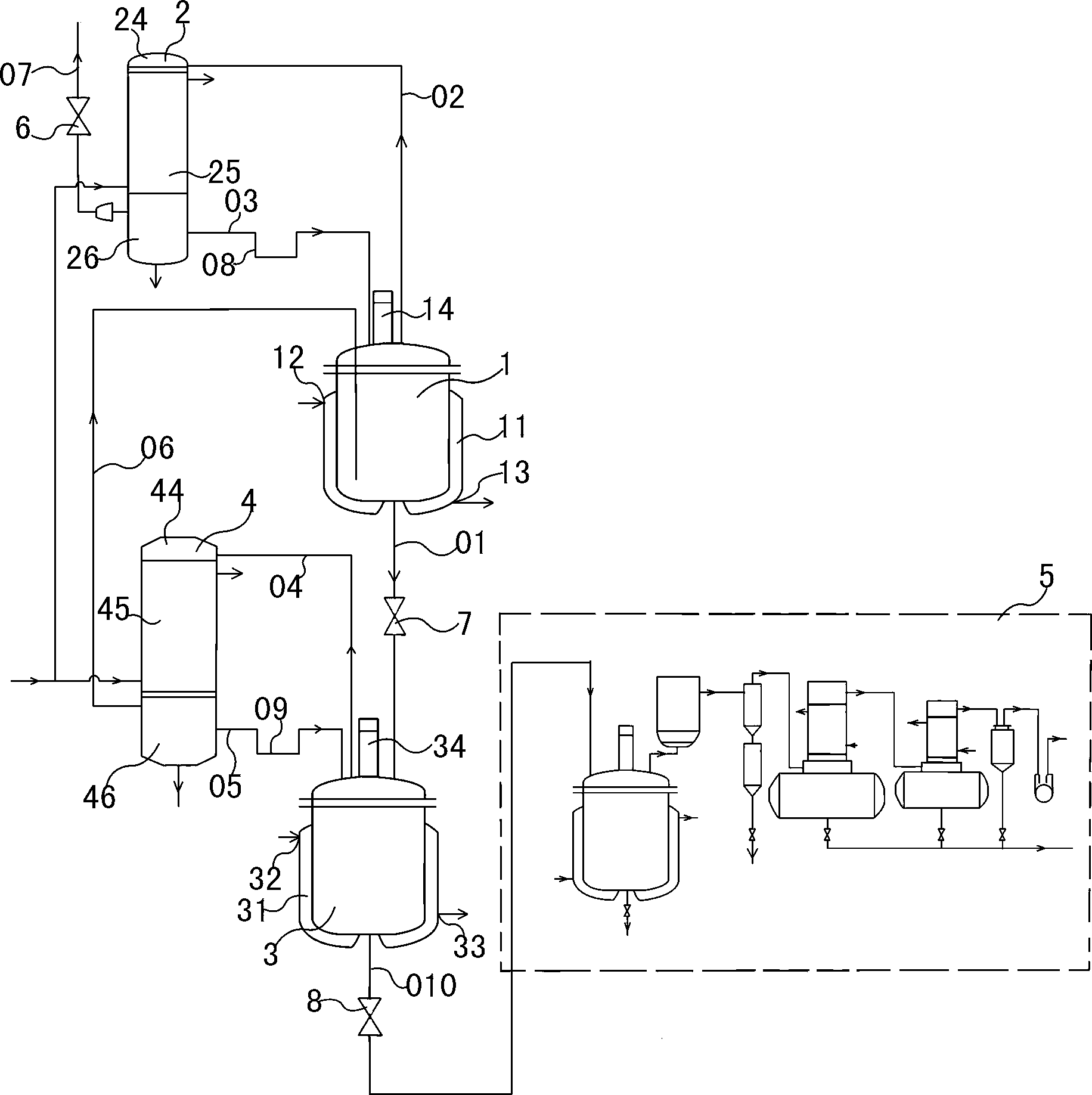
[0062] Such as figure 1 As shown, the phthalocyanine compound synthesis device includes a first reactor 1 , a first condenser 2 , a second reactor 3 , a second condenser 4 and a vacuum drying device 5 .

[0063] The cavity of the first reaction kettle 1 communicates with the cavity of the second reaction kettle 3 through the first material conveying pipe 01 .

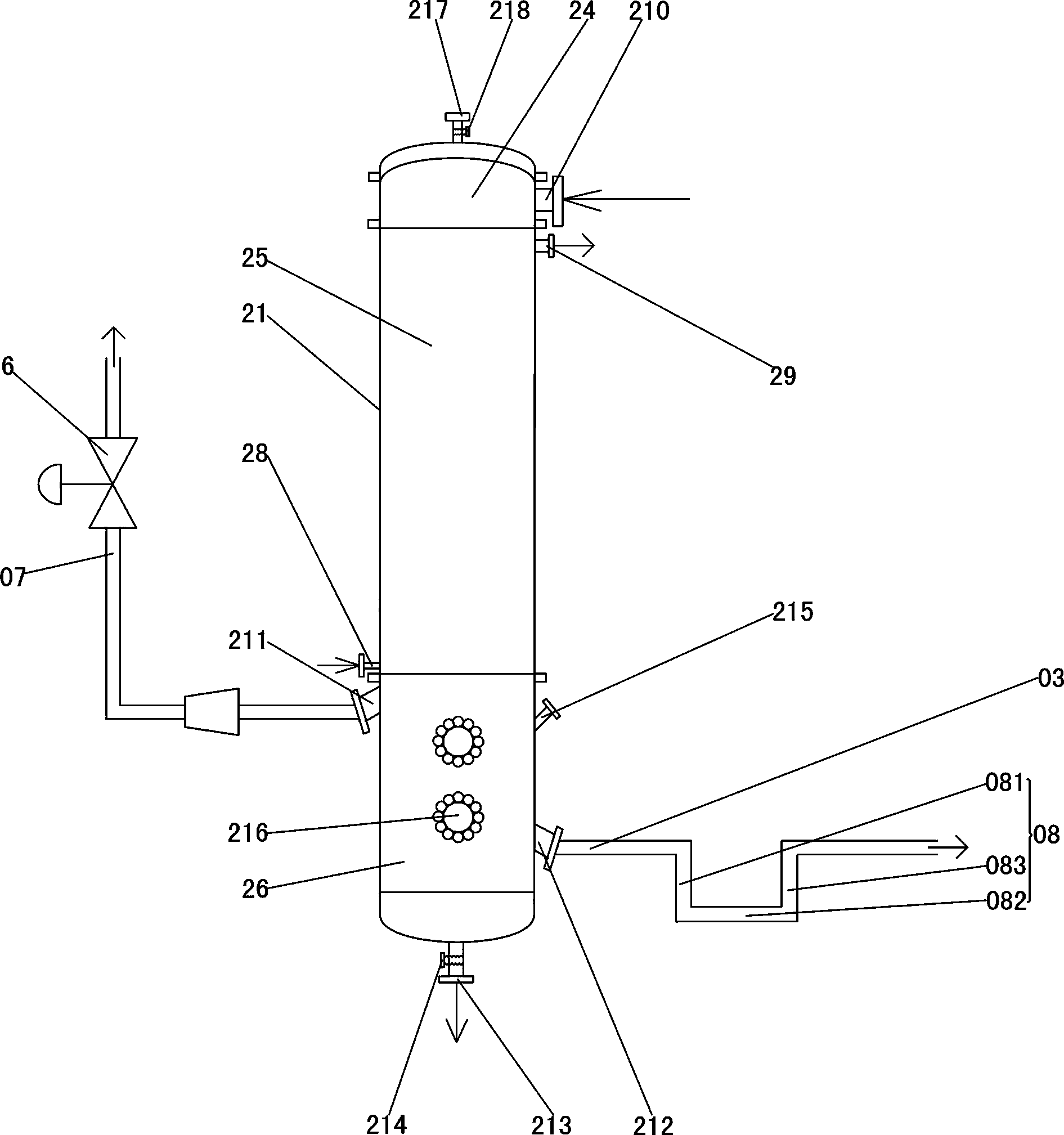
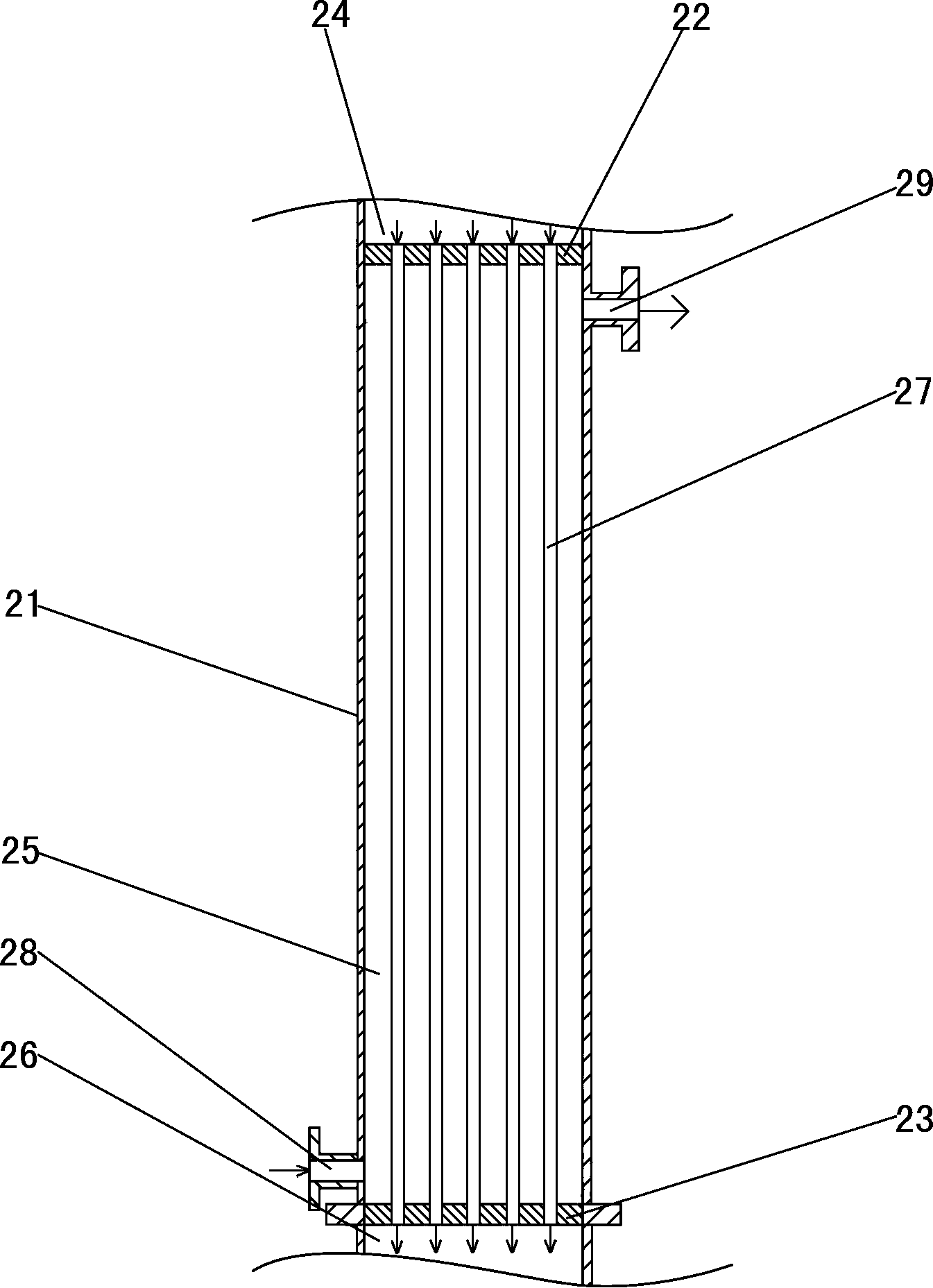
[0064] refer to figure 2 and image 3 , the first condenser 2 comprises a first condenser housing 21, a first upper partition 22 and a first lower partition 23 are arranged in the first condenser housing 21, the first upper partition 22 and the first lower partition The plate 23 divides the first condenser shell 21 into a first upper air chamber 24, a first condensation chamber 25 and a first liquid storage chamber 26 arranged from top to bottom, and a plurality of first condenser chambers 25 are provided with Heat exchange tube 27, the lower end of the first heat exchange tube 27 communicates with the cavity of the...

Embodiment 2

[0117] Such as Figure 9 As shown, the present embodiment is different from Embodiment 1 in that: in the vacuum drying device 5, the cyclone separator 53 is not provided between the buffer tank 52 and the third condenser 54, and the gas delivery pipe 503 is omitted. ; The steam outlet 522 of the buffer tank 2 communicates with the cavity of the third lower air chamber 546 through the gas delivery pipe 502 .

[0118] The rest of the structure of this embodiment is the same as that of Embodiment 1.

Embodiment 3

[0120] Such as Figure 10 As shown, the vacuum drying device of the present embodiment comprises a third reaction kettle 51, a third condenser 54, a first solvent recovery tank 55 and a vacuum pump 59, and the cavity of the third reaction kettle 51 is connected with the third downgas through the gas delivery pipe 501. The cavity of the chamber 546 is communicated, and the cavity of the third upper air chamber 544 is communicated with the vacuum pump 59 through the gas delivery pipe 506 . The positional relationship and connection relationship between the third condenser 54 and the first solvent recovery tank 55 are the same as those in Embodiment 1, and the rest of the structure of this embodiment is also the same as Embodiment 1.


PUM


Abstract

The invention discloses a phthalocyanine compound synthesizer. The phthalocyanine compound synthesizer comprises a first reaction kettle, a first condenser, a second reaction kettle and a second condenser, wherein the first reaction kettle is communicated with the second reaction kettle by a first material conveying tube; a first gas inlet, a first gas outlet, a first solvent reflux opening and a first water outlet are formed on the first condenser; the first reaction kettle is communicated with the first gas inlet by a first mixed gas conveying tube; the first solvent reflux opening is communicated with the first reaction kettle by the first solvent reflux tube; a second gas inlet, a second gas outlet, a second solvent reflux opening and a second water outlet are formed on the second condenser; the second reaction kettle is communicated with the second gas inlet by the second mixed gas conveying tube; the second solvent reflux opening is communicated with the second reaction kettle by the second solvent reflux tube; and the second gas outlet is communicated with the first reaction kettle by a third mixed gas conveying tube. The phthalocyanine compound synthesizer disclosed by the invention effectively controls generated moisture, improves ammonia gas yield, recycles a carrier solvent and ensures safety and continuity of operation.

Description

technical field [0001] The invention relates to equipment for producing phthalocyanine compounds, in particular to a phthalocyanine compound synthesis device suitable for producing phthalocyanine compounds by a two-step solvent method. Background technique [0002] The production methods of phthalocyanine compounds are divided into solid-phase method and solvent method. [0003] Due to the poor heat and mass transfer effect of the phthalocyanine compound produced by the solid phase method, it is difficult to fully mix the materials, and the temperature in the system is not uniform, so the product yield is low, the quality is poor, the color is not bright, and it is difficult to realize large-scale industrial production. [0004] The production of phthalocyanine compounds by solvent method is more widely used because of overcoming the above-mentioned shortcomings. The solvent method is divided into one-step method and two-step method. Compared with the one-step solvent meth...

Claims


Application Information

Patent Timeline
Patent Type & Authority Applications(China)
IPC IPC(8): B01J19/00B01J19/18C07D487/22
Inventor 蔡业豪郑少琴林红霞陈奕煌
Owner FUJIAN HUATIANYU SCI & TECH DEV
Why Eureka
Try Eureka