Entrained-flow bed gasification furnace for coal hydrogenation

An entrained bed and coal hydrogenation technology, applied in the field of gasifiers, can solve the problems of heavy dust removal load, large energy consumption, and large dust volume in the processing system, reduce hydrogen consumption, reduce the amount of fine powder, and improve heat utilization rate effect

Inactive Publication Date: 2014-03-26
SHANXI INST OF COAL CHEM CHINESE ACAD OF SCI
View PDF1 Cites 7 Cited by
  • Summary
  • Abstract
  • Description
  • Claims
  • Application Information

AI Technical Summary

Problems solved by technology

However, the circulation of a large amount of gas in this gasifier requires a lot of energy consumption. Whether the required circulation ratio can be achieved on an industrial scale by relying on the momentum of gas injection still needs to be verified by experiments. In additi

Method used


Image

  • Entrained-flow bed gasification furnace for coal hydrogenation
  • Entrained-flow bed gasification furnace for coal hydrogenation
  • Entrained-flow bed gasification furnace for coal hydrogenation

Examples


Embodiment 1

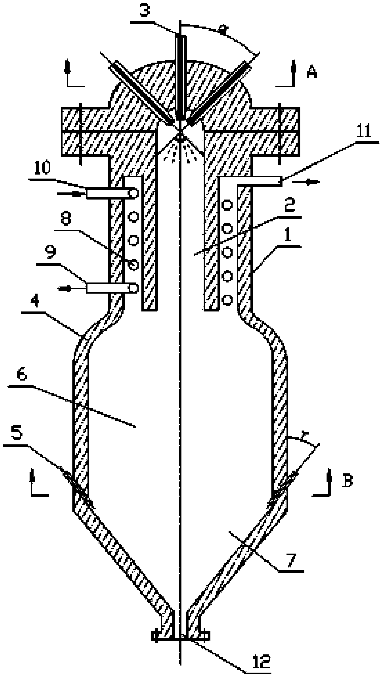
[0027] An entrained flow gasifier for coal hydrogenation, the gasifier is composed of a furnace body 1, a feed nozzle 3, a gasification chamber 2, and a semi-coke collection pool 7, and the inner wall of the furnace body 1 is coated with a refractory material 4 , the furnace body 1 is divided into upper, middle and lower parts, the upper part of the furnace body 1 is a vertical section, the middle part of the furnace body 1 is an enlarged section 6, the lower part of the furnace body 1 is a V-shaped semi-coke collection pool 7, and the furnace body 1 The upper part is the gasification chamber 2, a feed nozzle 3 is located at the center of the top of the gasification chamber 2, the outlet is vertically downward, and a preheating device for raw material gas is installed between the gasification chamber 2 and the upper part of the furnace body 1. The coil heat exchanger 8, the upper part of the coil heat exchanger 8 is provided with a low-temperature hydrogen inlet 10, the lower p...

Embodiment 2

[0030] The three feed nozzles 3 are evenly distributed at the top of the gasification chamber 2, the outlet is downward and the angle α with the center line of the furnace body 1 is 60° o Adjust the layout within the range, the lower part of the expansion section 6 of the furnace body 1 is provided with 5 high-pressure gas injection pipes 5, and the range of the angle γ between the outlet and the center line of the furnace body 1 is 45 o , the range of the angle β with the horizontal plane is 45 o . All the other are with embodiment 1.

Embodiment 3

[0032] 4 feeding nozzles 3, three of which are evenly distributed on the top of the gasification chamber 2, the outlet is downward and the angle α with the center line of the furnace body 1 is 30 o The arrangement is adjusted within the range, the other is at the center of the top of the gasification chamber 2, and the outlet is vertically downward. The lower part of the expansion section 6 of the furnace body 1 is provided with 6 high-pressure gas injection pipes 5, and the range of the angle γ between the outlet and the center line of the furnace body 1 is 60°. o , the range of the angle β with the horizontal plane is 30 o . All the other are with embodiment 1.


PUM


Abstract

The invention discloses an entrained-flow bed gasification furnace for coal hydrogenation, which consists of a furnace body (1), a feed nozzle (3), a gasification chamber (2) and a semi-coke collection tank (7) and is characterized in that the furnace body (1) is divided into an upper part, a middle part and a lower part; the upper part of the furnace body (1) is a vertical section; the middle part of the furnace body (1) is an expansion section (6); the V-shaped semi-coke collection tank (7) is arranged at the lower part of the furnace body (1); the gasification chamber (2) is arranged at the upper part of the furnace body (1); the feed nozzle (3) is positioned at the top end of the gasification chamber (2); a coil heat exchanger (8) for preheating the feed gas is arranged between the gasification chamber (2) and the upper part of the furnace body (1); a product gas outlet (11) is formed in the furnace body (1) above the coil heat exchanger (8); a high-pressure gas spray pipe (5) is arranged at the lower part of the expansion section (6) of the furnace body (1); a discharge port (12) is formed at the bottom of the semi-coke collection tank (7). The entrained-flow bed gasification furnace disclosed by the invention has the advantages of low energy consumption, low hydrogen consumption and light dedusting load.

Description

technical field [0001] The invention belongs to a gasifier, in particular to an entrained-bed gasifier for coal hydrogenation. Background technique [0002] With the acceleration of my country's urbanization process and the improvement of environmental protection requirements, the demand for natural gas is increasing year by year. In 2010, my country's natural gas consumption was 100 billion m 3 , with a gap of 10 billion m 3 . It is estimated that my country's natural gas gap will reach 100 billion m in 2020 3 . According to my country's energy situation, the production of SNG technology from coal is an effective means to make up for the shortage of natural gas resources. [0003] Conventional coal-to-natural gas technology (also known as two-step method) converts coal into synthesis gas (CO+H 2 ), the syngas is then methanated to obtain SNG. This process is relatively mature, and it has been industrialized in the Great Plains factory in the United States in the 1880...

Claims


Application Information

Patent Timeline
IPC IPC(8): C10J3/48C10J3/50C10J3/86
Inventor 毕继诚曲旋袁申富晁兵孙东凯
Owner SHANXI INST OF COAL CHEM CHINESE ACAD OF SCI
Why Eureka
Try Eureka