Heat exchange system

A technology of heat exchange system and heat exchanger, applied in the field of heat exchange system, can solve the problems of low utilization value, high energy consumption, underutilization, etc., and achieve the effect of simple structure, low investment cost and light weight

Active Publication Date: 2014-03-26
HUNAN JINSONG MACHINERY
View PDF7 Cites 5 Cited by
  • Summary
  • Abstract
  • Description
  • Claims
  • Application Information

AI Technical Summary

Problems solved by technology

[0012] Existing heat source towers discharge water vapor, which loses the latent heat of water vapor in the air and is not fully utilized. Moreover, it consumes part of the heat energy for concentrating the antifreeze; More consumption, less use value

Method used


Image

  • Heat exchange system

Examples


Embodiment 1

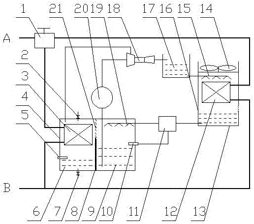
[0030] Two subsystems: a closed subsystem and an open subsystem.

[0031] The No. 1 heat exchanger 3 and the No. 2 heat exchanger 12 in the closed subsystem are connected in parallel by pipes, and the two ports A and B of the pipes are connected to the workstation.

[0032] The phase change device 4 in the open subsystem is a sealed box structure, which is divided into a condensation chamber 6 and a vaporization chamber 9 by a partition 8 and a steam louver 21. The partition 8 is located under the steam louver 21; the vaporization chamber 9 The liquid outlet of the liquid outlet is sequentially connected to the nozzle of the pump 20 and the ejector 18, and the negative pressure chamber of the ejector 18 is connected to the gas outlet of the condensation chamber 6; a liquid vapor nozzle 19 is installed above the vaporization chamber 9, and the inlet of the liquid vapor nozzle 19 is connected to a heating device 11, the liquid inlet of the heating device 11 is connected to the h...

Embodiment 2

[0036] On the basis of Example 1, a liquid diverter valve 1 is installed at the parallel inlets of the No. 1 heat exchanger 3 and the No. 2 heat exchanger 12 . In this embodiment, the liquid medium flowing through the No. 1 heat exchanger 3 and the No. 2 heat exchanger 12 is proportionally distributed through the liquid splitter valve 1 .

Embodiment 3、4

[0038] On the basis of Embodiment 1 and 2 respectively, air intake valve 2 and drain valve 7 are set above and below condensation chamber 6, and condensed water level sensor 5 is installed in condensation chamber 6, when condensed water level sensor 5 detects When the liquid level of the condensed water is higher than the set value, the intake valve 2 and the drain valve 7 are opened at the same time, and the intake is discharged; otherwise, the intake valve 2 and the drain valve 7 are both closed.


PUM


Abstract

Disclosed is a heat exchange system. The heat exchange system is composed of a closed subsystem and an open subsystem. A first heat exchanger of the closed subsystem and a second heat exchanger of the closed subsystem are connected in parallel through a pipeline. A phase change device of the open subsystem is divided into a condensation chamber and a vaporizing chamber through a partition plate and a steam shutter. A liquid outlet of the vaporizing chamber is connected with a pump and a nozzle of an ejector in sequence, and a negative pressure cavity of the ejector is connected with a steam outlet of the condensation chamber. A fluid steam nozzle is installed above the vaporizing chamber, an inlet of the fluid steam nozzle is connected with an outlet of a heating device, and a liquid inlet of the heating device is connected with a heat exchange tower; a liquid steam outlet of the ejector is connected with a non-seal type ejecting box, and a liquid outlet of the ejecting box is connected with a liquid nozzle installed in the heat exchange tower. The first heat exchanger is installed in the condensation chamber, and the second heat exchanger is installed below the liquid nozzle in the heat exchange tower. A liquid level sensor is installed in the vaporizing chamber and controls the working state of the heating device.

Description

technical field [0001] The invention relates to a heat exchange system capable of fully utilizing latent heat and sensible heat of liquid vapor. Background technique [0002] With the continuous growth of the population and the rapid development of the economy, the consumption and depletion of mineral energy have been exacerbated, and at the same time, serious pollution and damage have been brought to the environment. For this reason, people are finding the outlet of energy with great effort: the one, save energy, the 2nd, develop new energy. So far, on the one hand, energy-saving technology is based on the first law of thermodynamics, reducing various losses and wastes from the quantitative aspect; on the other hand, starting from the second law of thermodynamics, starting from the qualitative aspect, using low energy , land, water, solar energy, industrial waste heat, etc.) to replace a part of high-level energy (coal, oil, electric energy) to save high-level energy. The...

Claims


Application Information

Patent Timeline
Patent Type & Authority Applications(China)
IPC IPC(8): F25B30/06F25B49/00
Inventor 刘赟刘小江
Owner HUNAN JINSONG MACHINERY
Why Eureka
Try Eureka