Reflection cavity type confocal measuring method of super-large radius of curvature
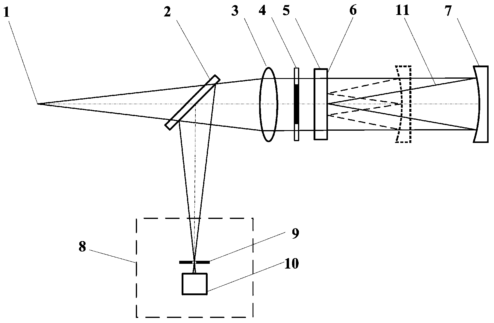
A technology of radius measurement and super curvature, which is applied in measurement devices, instruments, optical devices, etc., to achieve the effect of simple and compact measurement optical path, improved fixed focus sensitivity, and small moving distance
- Summary
- Abstract
- Description
- Claims
- Application Information
AI Technical Summary
Problems solved by technology
Method used
Image
Examples
Embodiment 1
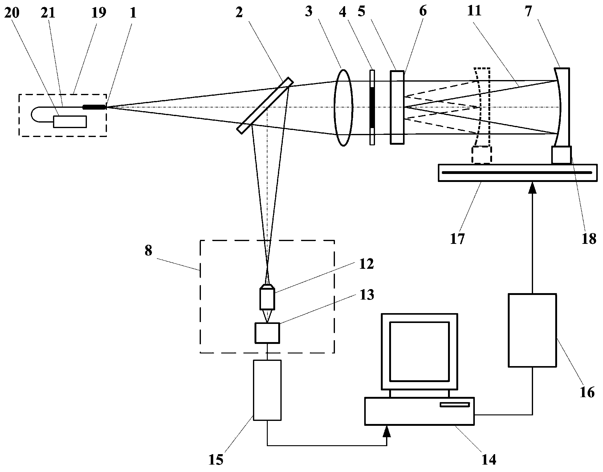
[0035] When the measured lens 7 is a concave lens with a diameter of D=150mm, the reflective cavity confocal ultra-large radius of curvature measuring device such as figure 2 As shown, the measurement steps are:
[0036] (a) Start the measurement software in the main control computer 14, turn on the laser 20, and the light emitted by the laser 20 is transmitted through the optical fiber 21 to form the point light source 1. The light emitted by the point light source 1 passes through the beam splitter 2 and the collimator lens 3 to form a parallel beam;
[0037] (b) The measured lens 7 is placed on the adjustment frame 18 , and the measured lens 7 is adjusted through the adjustment frame 18 so that it has a common optical axis with the collimator lens 3 . Parallel light is irradiated on the measured lens 7, and the measured lens 7 is converged to form a measuring beam 11 that is irradiated on the rear surface 6 of the parallel flat crystal;
[0038] (c) The measurement softw...
Embodiment 2
[0045] When the measured lens 7 is a concave lens with a diameter of D=150mm, the reflective cavity confocal ultra-large radius of curvature measuring device such as figure 2 As shown, the measurement steps are:
[0046] (a) Start the measurement software in the main control computer 14, turn on the laser 20, and the light emitted by the laser 20 is transmitted through the optical fiber 21 to form the point light source 1. The light emitted by the point light source 1 passes through the beam splitter 2 and the collimator lens 3 to form a parallel beam;
[0047] (b) The measured lens 7 is placed on the adjustment frame 18 , and the measured lens 7 is adjusted through the adjustment frame 18 so that it has a common optical axis with the collimator lens 3 . Parallel light is irradiated on the measured lens 7, and the measured lens 7 is converged to form a measuring beam 11 that is irradiated on the rear surface 6 of the parallel flat crystal;
[0048] (c) The measurement softw...
Embodiment 3
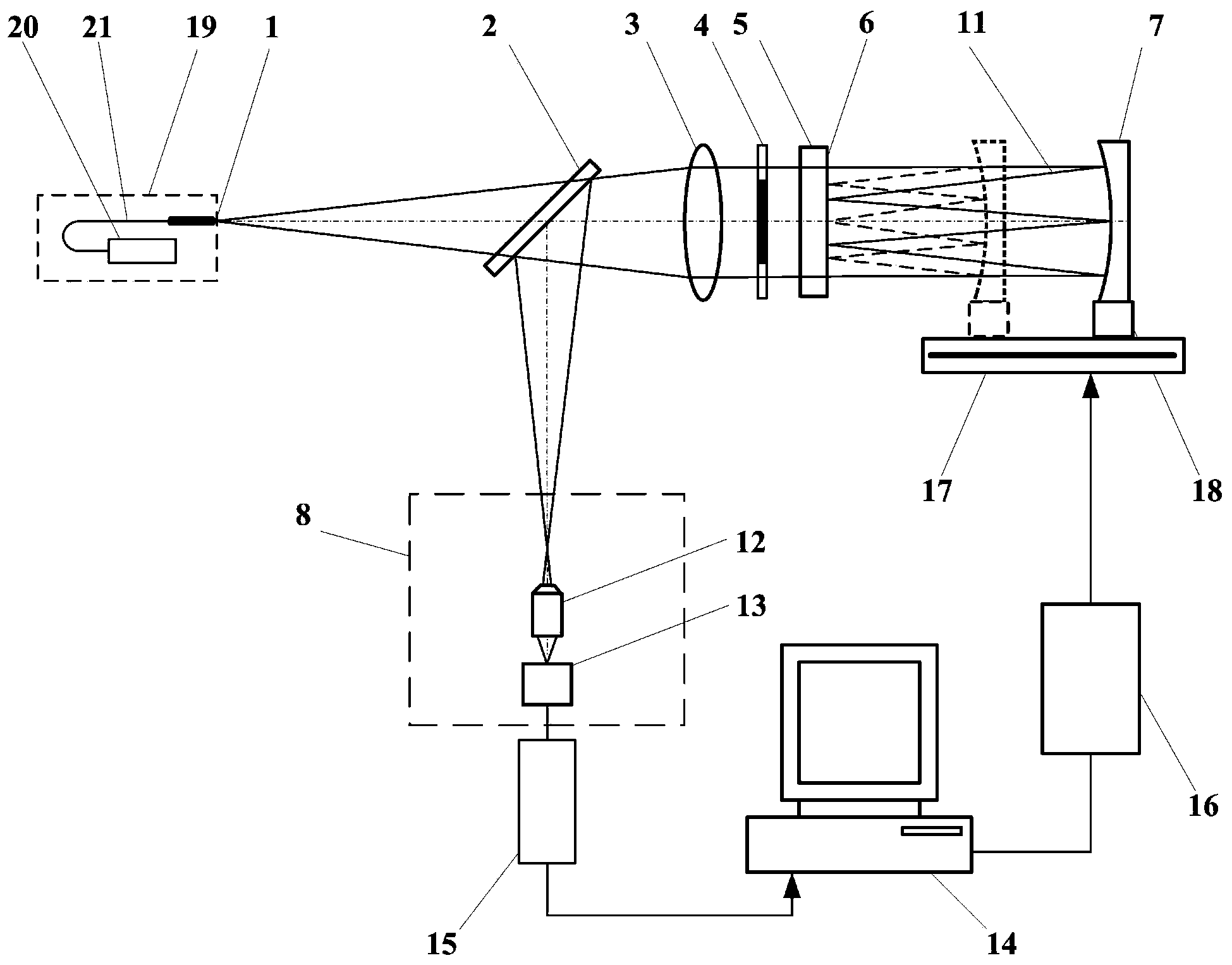
[0053] When the measured lens 7 is a concave lens with a diameter of D=150mm, the reflective cavity confocal ultra-large radius of curvature measuring device such as image 3 As shown, the measurement steps are:
[0054] (a) Start the measurement software in the main control computer 14, turn on the laser 20, and the light emitted by the laser 20 is transmitted through the optical fiber 21 to form the point light source 1. The light emitted by the point light source 1 passes through the beam splitter 2 and the collimator lens 3 to form a parallel beam;
[0055] (b) Place the lens under test 7 on the adjustment frame 27 , and adjust the lens under test 7 through the adjustment frame 27 so that it has a common optical axis with the collimator lens 3 . Parallel light is irradiated on the measured lens 7, and the measured lens 7 is converged to form a measuring beam 11 that is irradiated on the rear surface 6 of the parallel flat crystal;
[0056] (c) The measurement software in...
PUM
 Abstract
Description
Claims
Application Information
 - R&D
- Intellectual Property
- Life Sciences
- Materials
- Tech Scout
- Unparalleled Data Quality
- Higher Quality Content
- 60% Fewer Hallucinations
Browse by: Latest US Patents, China's latest patents, Technical Efficacy Thesaurus, Application Domain, Technology Topic, Popular Technical Reports.
© 2025 PatSnap. All rights reserved.Legal|Privacy policy|Modern Slavery Act Transparency Statement|Sitemap|About US| Contact US: help@patsnap.com


