Device and method for automatically matching laser radar receiving and transmitting optical axes

A laser radar and automatic matching technology, applied in the field of collimation system, can solve problems such as the influence of collimation accuracy, unsuitable collimation, and inability to perform data observation, etc., and achieve the effect of simple and convenient operation and high feasibility

Inactive Publication Date: 2014-03-26
UNIV OF SCI & TECH OF CHINA
View PDF5 Cites 20 Cited by
  • Summary
  • Abstract
  • Description
  • Claims
  • Application Information

AI Technical Summary

Problems solved by technology

Here we use the echo signal method, its main advantage is that it can accurately scan the actual change of the echo signal intensity caused by the offset of the emission optical axis, the main disadvantage is that the col

Method used


Image

  • Device and method for automatically matching laser radar receiving and transmitting optical axes
  • Device and method for automatically matching laser radar receiving and transmitting optical axes
  • Device and method for automatically matching laser radar receiving and transmitting optical axes

Examples


Embodiment Construction

[0022] The present invention will be described in detail below in conjunction with the accompanying drawings and specific embodiments.

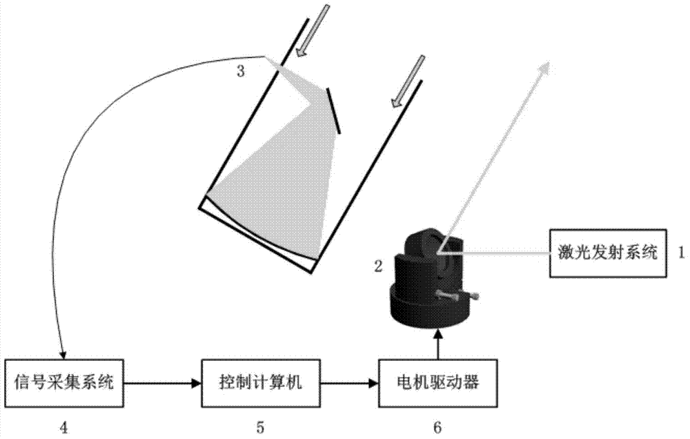
[0023] The structural schematic diagram of the automatic matching system of the laser radar receiving and receiving optical axis of the present invention is as follows figure 1 As shown, the beam emitted by the laser emitting system 1 passes through a unit 2 composed of a high-precision two-dimensional electric adjustment frame and a 60° total reflection mirror and finally enters the atmosphere. Under the control of the control computer 5, the two-dimensional adjustment frame is formed by Driven by two motors, it can move in two directions of tilt and rotation. The control computer 5 controls the two-dimensional electric adjustment frame 2 through the motor driver to make it scan in the two directions of tilt and rotation. At the same time, the radar data acquisition system 4 collects echoes at different scanning positions within a specified ...


PUM


Abstract

The invention provides a device and a method for automatically matching laser radar receiving and transmitting optical axes. The device comprises an emergent light path, a receiving light path and a data acquisition and control portion, an emergent system comprises a laser, a beam expanding system, a plurality of reflecting mirrors and lenses, laser light is emitted to air through the beam expanding system, the lenses, the reflecting mirrors and an optical antenna, a receiving system comprises a telescope, echo signals sequentially pass an optical fiber, the lenses, a light filter and a photoelectric detection element, the photoelectric detection element is arranged at an input end of a data acquisition system, and an output end of a control system controls the optical antenna with a high-accuracy servo motor through a motor driving controller. The method automatically traces the echo signals by the aid of a program design two-dimensional spiral scanning algorithm, uniaxial scanning and matrix scanning are performed to obtain the best emitting antenna position, so that an emitting antenna points to and receives collimation of the optical axis of the telescope, operators no longer need rich experience, and the method is simple and convenient to operate and high in feasibility.

Description

technical field [0001] The invention relates to the technical field of collimation systems, in particular to a laser radar receiving and receiving optical axis automatic matching device and method, which can automatically track echo signals and an automatic collimation system for two-dimensional rectangular scanning. Background technique [0002] At present, in order to detect the temperature and wind speed of the mesotope atmosphere, resonant fluorescence lidar is often used. It uses the resonant fluorescence scattering echo signal of the metal atomic layer at an altitude of 80-105km to detect the atmospheric temperature and wind field information in this altitude area. It mainly emits a laser with a very narrow ray width, uses the fluorescence spectral lines of metal atoms, and retrieves the atmospheric temperature and wind field by detecting the fluorescence signals at different positions of the spectral lines. [0003] In any laser radar system, it is necessary to ensur...

Claims


Application Information

Patent Timeline
IPC IPC(8): G01S7/497G01S17/95
CPCG01S7/4812G01S7/497G01S17/95Y02A90/10
Inventor 方欣李陶班超窦贤康
Owner UNIV OF SCI & TECH OF CHINA
Why Eureka
Try Eureka