Fixation member and fixation apparatus having the fixation member

A technology of fixing parts and fixing parts, applied in the fields of fixing parts and fixing devices, can solve the problems of wear, stick-slip, and lack of lubrication of sliding layers, and achieve the effect of improving wear resistance and sliding properties

Inactive Publication Date: 2014-03-26
NOK CORP +2
View PDF4 Cites 2 Cited by
  • Summary
  • Abstract
  • Description
  • Claims
  • Application Information

AI Technical Summary

Problems solved by technology

When the lubricant is squeezed out, there is a lack of lubrication between the inner peripheral surface of the fixing member and the pressing member, and stick-slip occurs, causing a problem of abrasion of the sliding layer

Method used


Image

  • Fixation member and fixation apparatus having the fixation member
  • Fixation member and fixation apparatus having the fixation member
  • Fixation member and fixation apparatus having the fixation member

Examples


Embodiment approach 1

[0041] The fixing member according to the present invention is applied to a fixing unit of an image forming apparatus, and is used in the fixing unit to fix an unfixed toner image on a recording medium by heat and pressure. In Embodiment 1, an endless fixing belt (endless belt or endless film) is exemplified as a fixing member.

[0042] figure 1 is a schematic cross-sectional view of the fixing belt. The fixing belt 1 has: a metal base 10 having at least one layer of seamless electroforming belt; a sliding layer 11 formed on the inner peripheral surface of the metal base 10; an elastic layer 12 formed on the outer peripheral surface of the metal base 10; The release layer 13 on the outer peripheral surface of 12 is sequentially laminated with the sliding layer 11, the metal substrate 10, the elastic layer 12, and the release layer 13 from the inside.

[0043] The metal base 10 has at least one layer of seamless electroformed strip of nickel or nickel alloy with excellent the...

Embodiment approach 2

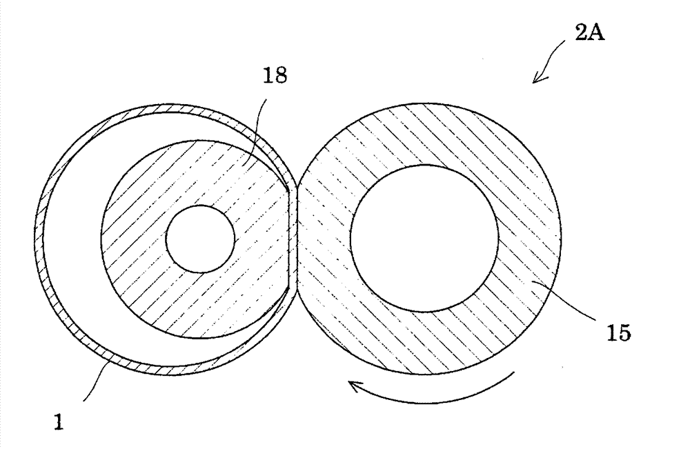
[0077] Embodiment 2 is a modified example of the configuration of the fixing device, and the same components as those in Embodiment 1 are assigned the same reference numerals, and redundant descriptions are omitted. image 3 It is a schematic sectional view showing the fixing device according to the second embodiment.

[0078] Such as image 3 As shown, fixing device 2A includes: fixing belt 1 ; pressure roller 15 disposed opposite to fixing belt 1 ; and fixing roller 18 pressing fixing belt 1 against pressure roller 15 from inside instead of pressing member 14 . In addition, a heating unit for heating the fixing belt 1 may be built in the fixing roller 18 or may be arranged outside the fixing belt 1 .

Embodiment approach 3

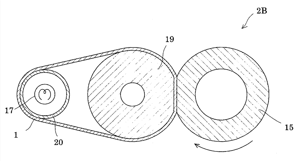
[0080] Embodiment 3 is a modified example of the configuration of the fixing device, and the same components as those in Embodiment 1 are assigned the same reference numerals, and redundant descriptions are omitted. Figure 4 It is a schematic cross-sectional view showing a fixing device according to Embodiment 3. FIG.

[0081] Such as Figure 4 As shown, the fixing device 2B includes: a fixing belt 1; a pressure roller 15 arranged to face the fixing belt 1; an inner roller 19 that presses the fixing belt 1 against the pressure roller 15 from the inside; and a heating roller with a built-in heating unit 17. 20. Inside the fixing belt 1 , an inner roller 19 and a heating roller 20 with a built-in heating unit 17 are arranged, and the fixing belt 1 is rotationally driven by the inner roller 19 and the heating roller 20 . In addition, in this case, the heating unit 17 of the heating roller 20 may be arranged outside the fixing belt 1 .
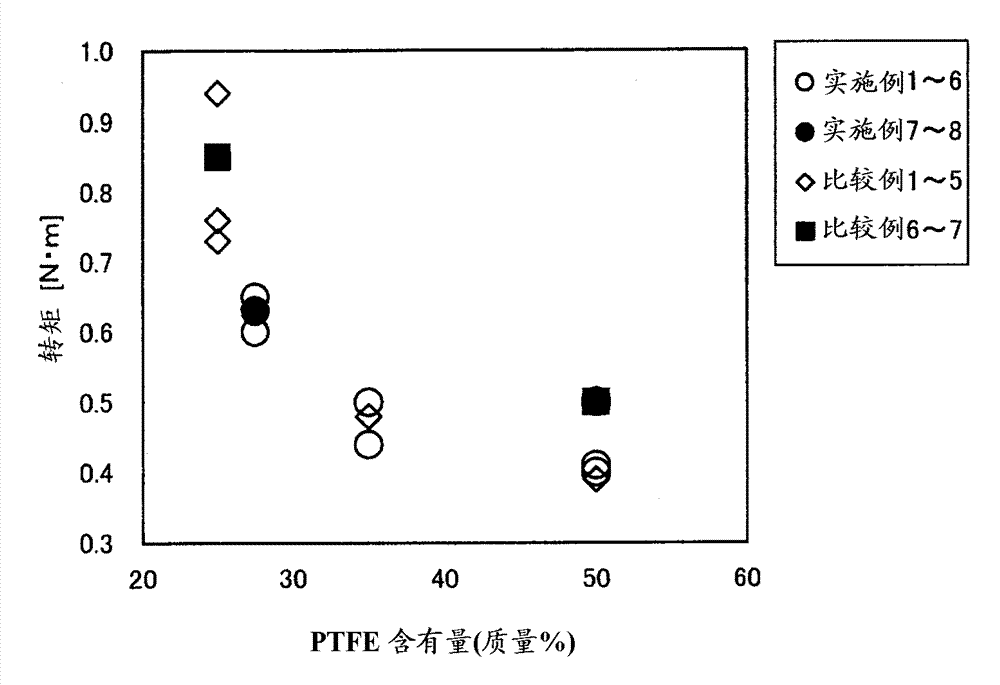
[0082] (Example)

[0083] Hereinafter,...


PUM


Abstract

The present invention relates to a fixation member and a fixation apparatus having the fixation member. The present invention provides a fixation member which exhibits enhanced wear resistance and sliding property between the peripheral surface of the fixation member and a pressure member, which can reduce driving torque at a fixation unit, and which does not cause stick slipping even in a high-load operational mode, and a fixation apparatus having the fixation member. The fixation member (1) employed in a fixation unit of the fixation apparatus has a metallic substrate (10) having at least one layer of an electrocast seamless belt, and a slide layer (11) disposed on the inner peripheral surface of the metallic substrate (10), wherein the slide layer (11) is formed of at least one species of the group consisting of a polyamide-imide resin and a polyimide resin, and a fluororesin; the slide layer (11) has a fluororesin content of 27.5 mass% to 50 mass%; and the slide layer (11) has a surface roughness Ra of 0.4 [mu]m or less.

Description

technical field [0001] The present invention relates to a fixing member and a fixing device including the fixing member, and is particularly applicable to a fixing unit of image forming devices such as copiers, facsimile machines, and laser printers. Background technique [0002] In a fixing device equipped with an image forming apparatus, it is configured to include: an endless fixing belt (fixing member); a pressure roller arranged to face the fixing member; The position where the rollers face each other is a predetermined nip portion that presses the fixing member against the pressure roller from the inside. [0003] In such a fixing device, it is known that the inner peripheral surface of the fixing member and the pressing member provided inside the fixing member slide, causing wear on the mutual surfaces. Therefore, usually, a lubricant such as silicone oil or fluorine-based grease is interposed between the two to maintain wear resistance. However, even if such a lubr...

Claims


Application Information

Patent Timeline
Patent Type & Authority Applications(China)
IPC IPC(8): G03G15/20
CPCG03G15/2057G03G2215/2035
Inventor 杉山新五铃木雅也西田晃冈部均北原哲宏山崎裕次郎
Owner NOK CORP
Why Eureka
Try Eureka