A high-voltage esd protection device with double anti-latch-up ring ldmos-scr structure
What is Al technical title?
Al technical title is built by PatSnap Al team. It summarizes the technical point description of the patent document.
A LDMOS-SCR, ESD protection technology, applied in electric solid devices, semiconductor devices, electrical components, etc., can solve the problems of low trigger voltage, weak anti-latch ability, etc., achieve low trigger voltage, increase area, improve maintenance The effect of voltage
Active Publication Date: 2015-12-30
NANTONG JIANGHUA MASCH CO LTD
View PDF7 Cites 0 Cited by
Summary
Abstract
Description
Claims
Application Information
AI Technical Summary
This helps you quickly interpret patents by identifying the three key elements:
Problems solved by technology
Method used
Benefits of technology
Problems solved by technology
Aiming at the problem of weak latch-up resistance in the existing high-voltage ESD protection technology, this paper proposes a technical solution with high sustain voltage, high sustain current, low trigger voltage and strong robustness, which can enhance the on-chip power integrated circuit system reliability
Method used
Image
Click on the blue label to locate the original text in one second.
Reading with bidirectional positioning of images and text.
Examples
Embodiment Construction
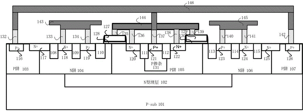
[0027] The present invention proposes a high-voltage ESD protection device with a double anti-latch-up annular LDMOS-SCR structure. Because it is mainly used in the field of high-voltage ESD protection, it needs to be based on a high-voltage BCD process platform, through reasonable design and control of certain features of the device layout parameters, ESD protection devices with different specifications that can meet various high-voltage ESD protection requirements can be prepared.
[0028] A high-voltage ESD protection device with double anti-latch-up annular LDMOS-SCR structure, which includes the ESD current discharge path of the LDMOS-SCR structure and the ESD current discharge path of Zener breakdown, and the layout of the annular LDMOS-SCR structure designed to increase hold voltage, hold current, and enhance ESD robustness of the device. It is characterized by: including P-type substrate 101, N-type buried layer 102, first P well 103, first N well 104, second P well 105,...
PUM
Abstract
The invention discloses a high-voltage ESD protective device with dual latch-up resistance and of an annular LDMOS-SCR structure. The high-voltage ESD protective device with the dual latch-up resistance and of the annular LDMOS-SCR structure can be applied to an on-chip IC. The high-voltage ESD protective device with the dual latch-up resistance and of the annular LDMOS-SCR structure comprises a P type substrate, an N type buried layer, a first P trap, a first N trap, a second P trap, a P adulterant, a second N trap, a third P trap, an isolation area, a first P+, a first N+, a second N+, a second P+, a third N+, a third P+, a fourth N+, a fourth P+, a fifth N+, a sixth N+, a fifth P+, a metal anode and a metal cathode, wherein a Zener breakdown ESD current discharging path is formed by the second N+, the second P+, the first N+ and the first P+ or by the fourth P+, the fifth N+, the sixth N+ and the fifth P+. According to the high-voltage ESD protective device with the dual latch-up resistance and of an annular LDMOS-SCR structure, the ESD robustness of the device can be improved, the maintaining voltage can be improved, and the trigger voltage can be reduced; due to the design of the annular layout of the LDMOS-SCR structure, the on resistance can be reduced, and the maintaining current can be improved; the ESD protective capacity of the dual latch-up resistance is achieved.
Description
technical field [0001] The invention belongs to the field of electrostatic protection of integrated circuits and relates to a high-voltage ESD protection device, in particular to a high-voltage ESD protection device with a double anti-latch ring LDMOS-SCR structure, which can be used to improve the reliability of on-chip IC high-voltage ESD protection. Background technique [0002] With the widespread use of automotive electronics, handheld terminals, high-speed USB interfaces, and tablet electronics, consumer electronics are facing increasingly severe challenges to system reliability. Static electricity is a common physical phenomenon. With the rapid development of integrated circuits and the wide application of polymer materials in recent years, the damage caused by the force, discharge and induction of static electricity is very serious. According to the statistics of the relevant departments of the United States, the annual loss of the US electronics industry due to elec...
Claims
Application Information
Patent Timeline
Application Date:The date an application was filed.
Publication Date:The date a patent or application was officially published.
First Publication Date:The earliest publication date of a patent with the same application number.
Issue Date:Publication date of the patent grant document.
PCT Entry Date:The Entry date of PCT National Phase.
Estimated Expiry Date:The statutory expiry date of a patent right according to the Patent Law, and it is the longest term of protection that the patent right can achieve without the termination of the patent right due to other reasons(Term extension factor has been taken into account ).
Invalid Date:Actual expiry date is based on effective date or publication date of legal transaction data of invalid patent.