Check patentability & draft patents in minutes with Patsnap Eureka AI!

Electric cooker control circuit with simplified direct-current power supply structure

A technology of DC power supply and control circuit, which is applied in the field of rice cooker control circuit of small household appliances and products similar to the load of the rice cooker. The effect of low cost and simple circuit structure

Active Publication Date: 2014-03-26
GUANGDONG REAL DESIGN INTELLIGENT TECH
View PDF5 Cites 0 Cited by
  • Summary
  • Abstract
  • Description
  • Claims
  • Application Information

AI Technical Summary

Problems solved by technology

[0004] The object of the present invention is to provide a control circuit for an electric cooker with a simplified DC power supply structure in order to solve the problem of complex structure and high cost of the control circuit of the prior art electric cooker products. Features of low cost

Method used


Image

  • Electric cooker control circuit with simplified direct-current power supply structure
  • Electric cooker control circuit with simplified direct-current power supply structure
  • Electric cooker control circuit with simplified direct-current power supply structure

Examples


specific Embodiment 1

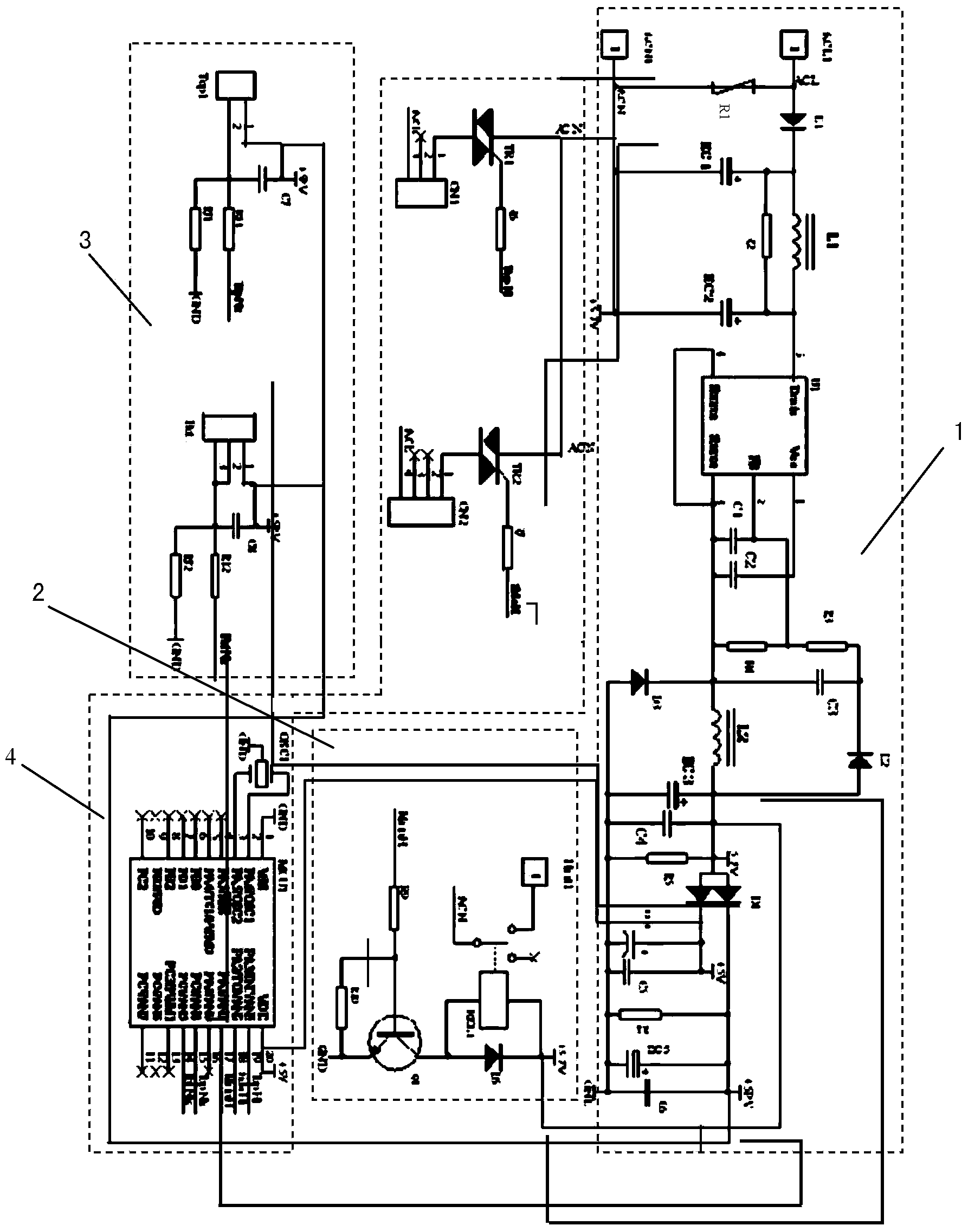
[0023] refer to figure 1 , the present embodiment 1 includes a DC power supply unit 1, a relay control unit 2, a sensor sampling unit 3 and a single-chip control unit 4, the DC power supply unit 1 is provided with a mains AC input terminal and a +5V DC output terminal, and the +5V DC output terminal of the DC power supply unit 1 The 5V DC output terminal is directly connected to the power input terminal of the relay control unit 2, the sensor sampling unit 3 and the single-chip control unit 4, forming a +5V DC single power supply DC power supply loop structure; the relay control unit 2, the sensor sampling unit 3 and the single-chip microcomputer control Each unit 4 has a +5V DC power supply adaptation structure; the output end of the sensor sampling unit 3 is connected to the input end of the single-chip control unit 4, and the output end of the single-chip control unit 4 is connected to the control input end of the relay control unit 2, and the single-chip control unit 4 acco...

specific Embodiment 2

[0033] refer to figure 2 , the characteristics of this embodiment are: the step-down circuit 1 adopts the switch chip SC1117DG, and the mains 220V often switches the chip SC1117DG to step down and output, forming a voltage of 5.7V to supply power for the relay.

[0034] The DC power supply unit 1 is composed of an AC-DC step-down rectifier module, diodes D1-D4, polarized capacitors EC1-EC6, resistors R1-R5, step-down chip U1, capacitors C1-C3 and inductors L1-L2; the step-down chip Pin 4 of U1 is connected to the positive terminal of resistor R1, inductor L1, and polarized capacitor EC2; the other end of resistor R1 is connected to the negative pole of diode D1, inductor L1, and the positive pole of polarized capacitor EC1; the positive pole of diode D1 is connected to the mains live wire ACL, the other end of the polarized capacitor EC1-EC2 is connected to the neutral line CAN of the mains; the 2-pin of the step-down chip U1 is connected to one end of the resistor R2-R3; the...

specific Embodiment

[0036] The characteristics of other specific embodiments of the present invention are: the relay control unit 2 is composed of resistors R1-R2, diode D1, triode Q1, +5V relay REL1 and insert Heat1; the sensor sampling unit 3 is composed of resistors R4- R5, capacitor C1 and socket BOT1 are formed; the single-chip microcomputer control unit 4 is composed of single-chip microcomputer chip MCU, resistor R3, thyristor TR1, socket CN3 and its peripheral oscillating circuit and reset circuit. All the other are with specific embodiment 1.

[0037] As can be seen from the technical content described above, the present invention abandons the two-stage step-down circuit in which the traditional mains 220V is stepped down to 12V for relay work, and then 12V is reduced to 5V for other loads to work; instead, the relay uses 5V to work Voltage, the mains 220V is directly stepped down to 5V DC by the step-down circuit, which is used for the relay drive circuit, sensor sampling circuit and si...


PUM


Abstract

The invention relates to an electric cooker control circuit with a simplified direct-current power supply structure. The electric cooker control circuit with the simplified direct-current power supply structure comprises a direct-current power supply unit, a relay control unit, a sensor sampling unit and a single-chip microcomputer control unit. The electric cooker control circuit with the simplified direct-current power supply structure is characterized in that the direct-current power supply unit is provided with a mains supply alternating-current input end and a +5V direct-current output end, wherein the +5V direct-current output end of the direct-current power supply unit is directly connected with the power input end of the relay control unit, the power input end of the sensor sampling unit and the power input end of the single-chip microcomputer control unit so that a direct-current power supply loop structure with electricity supply from a single +5V direct-current power source can be formed; the relay control unit, the sensor sampling unit and the single-chip microcomputer control unit are respectively provided with a +5V direct-current power source adaptive structure; the output end of the sensor sampling unit is connected with the input end of the single-chip microcomputer control unit, the output end of the single-chip microcomputer control unit is connected with the control input end of the relay control unit, and the single-chip microcomputer control unit has control over connection and disconnection of the relay control unit according to detection signals of a sensor so as to have control over the working state of the load. The electric cooker control circuit with the simplified direct-current power supply structure has the advantages of being simple in circuit structure, small in number of electronic components, low in cost, convenient to maintain and the like.

Description

Technical field: [0001] The invention relates to an electric rice cooker control circuit with a simplified direct current power supply structure, which is suitable for small household appliance electric cookers controlled by single-chip microcomputers and products with loads similar to electric rice cookers. It belongs to the technical field of small household electrical appliances. Background technique: [0002] At present, in the field of small household appliances, when most electric cookers are designed, because relays are used to control the work of the heating plate and the designed step-down circuit, it is necessary to reduce the voltage from the mains to rectify to 12V DC power supply to meet the needs of 12V relays. Operating Voltage. The working voltage of the general single-chip microcomputer chip is 5V-3V DC. In order to meet the working voltage requirements of the single-chip microcomputer, the 12V DC must be stepped down to 5V-3V DC. This requires adding a DC ...

Claims


Application Information

Patent Timeline
IPC IPC(8): H02M7/04
Inventor 汪军王强
Owner GUANGDONG REAL DESIGN INTELLIGENT TECH
Features
  • R&D
  • Intellectual Property
  • Life Sciences
  • Materials
  • Tech Scout
  • Unparalleled Data Quality
  • Higher Quality Content
  • 60% Fewer Hallucinations
Learn More