Inductive brushless direct current motor drive method

A technology of brushed DC motor and driving method, which is applied in the direction of electronically commutated motor control, single motor speed/torque control, electrical components, etc., and can solve problems such as increased noise, decreased qualified rate of motor production, and position deviation of Hall elements. , to achieve the effect of improving reliability, improving yield rate, and reducing the influence of position error

Active Publication Date: 2014-03-26
FORTIOR TECH SHENZHEN
View PDF5 Cites 14 Cited by
  • Summary
  • Abstract
  • Description
  • Claims
  • Application Information

AI Technical Summary

Problems solved by technology

[0004] The purpose of the present invention is to overcome the defect that the position deviation of the Hall element of the current brushless DC motor is caused by various reasons, which leads to a decrease in the production pass rate of the motor and an increase in noise, and to provide a sensory brushless motor that can completely solve the above defects. DC motor drive method

Method used


Image

  • Inductive brushless direct current motor drive method
  • Inductive brushless direct current motor drive method
  • Inductive brushless direct current motor drive method

Examples


Embodiment 1

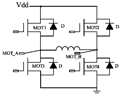
[0043] Such as Figure 1~6 As shown, the driving system of the present invention is composed of the coil of the motor and an H-type single-phase drive bridge, wherein the H-type single-phase drive bridge is composed of field effect transistor MOT1, field effect transistor MOT2, field effect transistor MOT3 and field effect The tube MOT4 is composed together, that is, the field effect tube MOT1 is connected in series with the field effect tube MOT3, the field effect tube MOT2 is connected in series with the field effect tube MOT4, and the drains D of the field effect tube MOT1 and the field effect tube MOT2 are jointly connected with the input voltage Vdd The source S of the field effect transistor MOT3 and the field effect transistor MOT4 is connected and grounded. The bridge point (i.e. the connection point) between the field effect transistor MOT1 and the field effect transistor MOT3 and the bridge point (i.e. the connection point) between the field effect transistor MOT2 an...

Embodiment 2

[0067] Embodiment 1 is to judge the conversion process between the sensory and non-sensory driving modes of the present invention according to the motor speed, and this embodiment is to determine the conversion between the sensory and non-sensory driving modes according to the PWM duty cycle control voltage The process, that is, the first embodiment uses the motor speed to adjust the starting mode, while the present embodiment uses the PWM control voltage to adjust.

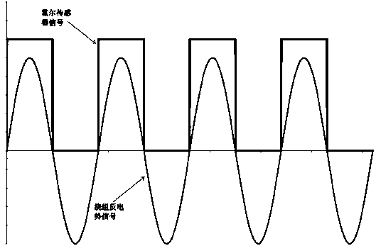
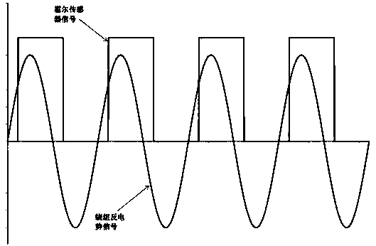
[0068] Such as Figure 7-9 as shown, Figure 8 , Figure 9 The waveforms of the driving voltage when the duty cycle of the PWM in the driving area is 100% and 50% are respectively shown. The driving current formed by this method is naturally optimal.

[0069] Its specific process is as Figure 9 As shown, the following steps are involved:

[0070] (1) After turning on the power, the system automatically enters the sensored motor start mode, and then operates in the sensored drive mode;

[0071] (2) The syste...


PUM


Abstract

The invention discloses an inductive brushless direct current motor drive method which is characterized by comprising the following steps: (1) after a power supply is started, a system automatically enters an inductive motor starting mode and then operates in an inductive drive mode; (2) the system calculates the rotating speed n of a motor according to a signal of a rotor position sensor; and (3) whether the rotating speed n of the motor is more than the threshold rotating speed na, at which the preset inductive drive is converted to noninductive drive, is judged, etc. The inductive brushless direct current motor drive method not only effectively reduces the influences of the position error of a Hall sensor on the operating efficiency and the noises of the brushless direct current motor, but also effectively increases the yield of production of a single-phase brushless direct current motor, so that the production cost of the motor is lowered.

Description

technical field [0001] The invention relates to a drive system, in particular to a drive method for a brushless DC motor with sense. Background technique [0002] Brushless DC motors (hereinafter referred to as motors) are widely used in fields such as computer cooling fans and washing machine drain pumps due to their low cost of motors and drivers, and their relatively simple structure. In actual use, this type of single-phase motor usually uses a Hall element as a sensor of the rotor position of the motor, so as to generate a control signal required for switching current according to the rotor position. [0003] In order to ensure the accuracy of its control signal, these Hall elements must be accurately and reliably installed near the rotor magnet of the motor to ensure that the Hall element can accurately and reliably detect the change of the magnetic field of the rotor magnet. If the position of the Hall element deviates, not only the efficiency of the motor will decre...

Claims


Application Information

Patent Timeline
Patent Type & Authority Applications(China)
IPC IPC(8): H02P6/06
CPCH02P6/16H02P6/14H02P6/15H02P6/181H02P6/20
Inventor 毕磊
Owner FORTIOR TECH SHENZHEN
Why Eureka
Try Eureka