
Helium vapor magnetic resonance magnet

A magnetic resonance and magnet technology, applied in the direction of magnetic objects, superconducting magnets/coils, measuring magnetic variables, etc., can solve the problems of complex design and manufacturing, and achieve the effect of simple flow and high thermal efficiency

Active Publication Date: 2014-03-26
KONINKLJIJKE PHILIPS NV
View PDF5 Cites 1 Cited by
  • Summary
  • Abstract
  • Description
  • Claims
  • Application Information

AI Technical Summary

Problems solved by technology

This extreme temperature difference creates design and manufacturing complexities

Method used


Image

  • Helium vapor magnetic resonance magnet
  • Helium vapor magnetic resonance magnet
  • Helium vapor magnetic resonance magnet

Examples


Embodiment Construction

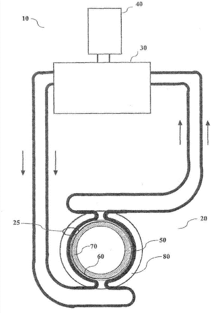
[0022] refer to figure 1 , shows an embodiment of a magnetic resonance (MR) magnet in a closed loop system 10 . Closed loop system 10 includes circulating helium vapor heated by MR magnet assembly 20 and cooled by cryocooler heat exchanger 30 with associated cryocooler 40 and recirculated to magnet assembly 20 . A suitable refrigerator heat exchanger with an associated cryogenic refrigerator is described in US2008 / 0209919.

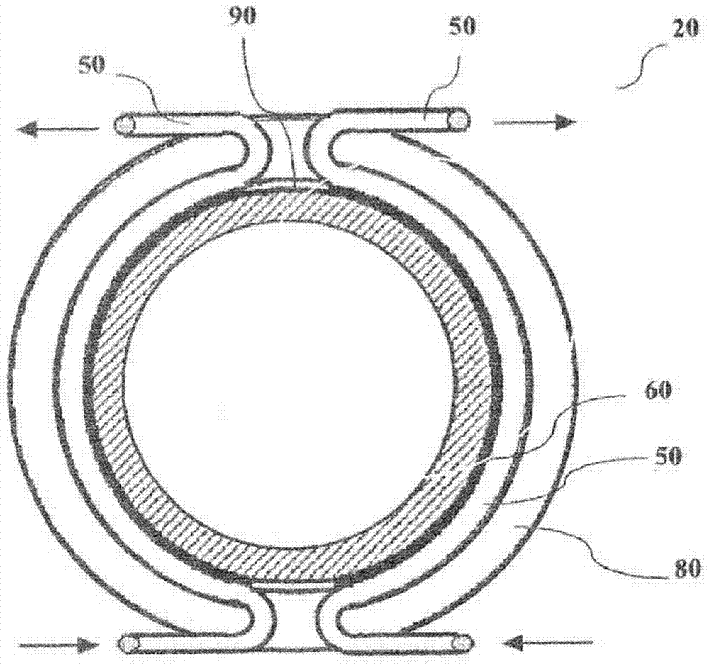
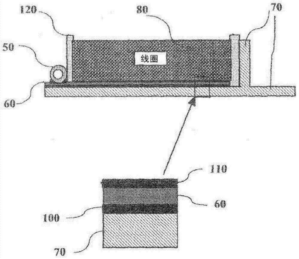
[0023] Cooled helium gas enters the magnet assembly 20 at the bottom and flows up to the heat pipe 50 attached to the heat conducting sheet 60 or plate inside the magnet. The helium vapor is cooled to about 4.2°K in heat exchanger 30, which provides a 1°K margin below the critical temperature of the magnet. The cold gas from the cryocooler heat exchanger 30 is relatively dense, but becomes less dense as it is heated by the magnet assembly 20, producing denser helium gas from the cryocooler heat exchanger 30 down to the bottom of the magnet. The upward f...


PUM


Abstract

A magnetic resonance magnet assembly 20 has a coil form 70 shaped as a hollow cylinder. At least two thermally conductive sheets 60 are disposed circumferentially around the coil form 70, separated by a non-electrically conductive region 90. Thermally conductive tubing 50 affixed to each thermally conductive sheeting section 60 runs circumferentially around the coil form 70. At least one layer of thermally conductive electrically insulating material 110 such as fiber glass is bonded with a thermally conductive epoxy encapsulant to the thermally conductive sheets 60. A winding of superconductive wire 80 is bond together and to the electrically insulating material 110 with the thermally conductive epoxy encapsulant.

Description

technical field [0001] The present application relates to magnetic resonance magnets, cryogenic magnets, superconducting magnets and in particular to the cooling of such magnets. Background technique [0002] Magnetic resonance (MR) scanners use superconducting magnets that are cooled to superconducting temperatures, eg less than 5.2° Kelvin. Traditionally, liquid helium has been used to cool superconducting magnets due to its thermal properties. However, liquid helium is expensive. In many parts of the world there is no steady supply of liquid nitrogen or alternatively liquid helium. [0003] The electrical and magnetic properties of the magnet are maintained while cooling the magnet to generate a uniform static magnetic field in the magnetic resonance system. The cooling system cools the coils evenly without compromising the integrity of the magnetic coils. [0004] The magnet coils used for whole-body MR imaging have bores large enough to accommodate the patient being...

Claims


Application Information

Patent Timeline
IPC IPC(8): G01R33/3815H01F6/04
CPCG01R33/3815H01F6/06G01R33/3802H01F6/04Y10T29/49071
Inventor R·A·阿克曼R·L·弗兰克
Owner KONINKLJIJKE PHILIPS NV
Learn More