Mixed-flow type water pump turbine

A pump-turbine, mixed-flow technology, applied in the field of mixed-flow pump-turbine, can solve problems such as instability, de-flow, hydraulic loss, and large secondary flow loss, and achieve the possibility of reducing vibration, improving flow performance, and secondary flow. The effect of small flow loss

Inactive Publication Date: 2014-04-02
ELECTRIC POWER RES INST OF GUANGDONG POWER GRID +1
View PDF10 Cites 15 Cited by
  • Summary
  • Abstract
  • Description
  • Claims
  • Application Information

AI Technical Summary

Problems solved by technology

Compared with conventional units, the working conditions are more complex and changeable
However, the existing pump turbines still have the following defects: (1) the runner blades of the pump turbine are generally 7 or 9, the space at the runner outlet is small, and the hydraulic loss and secondary flow loss are very large, which seriously affects the pump turbine. (2) Due to the special purpose of the pumped storage power station, the unit inevitably operates at a point deviated from the design condition. For example, in the partial load area, the dynamic and static interference phenomenon of the runner inlet of the turbine is severe, and the pressure fluctuation of the draft tube is also large , especially in the S area, the instability of the operating conditions is extremely prominent; (3) due to the serious shedding of the back of the runner blades, a series of problems such as high-intensity cavitation at the runner inlet are caused, which seriously affect the performance of the pumped storage power station. Safe and stable operation and economic benefits
However, the runner with long and short blades also has the following disadvantages: due to the long flow path between the blades of the pump turbine, the flow vortex generated between the blades in the "S" area is very serious, which has an important impact on the stability of the flow field and the stability of the unit operation. Still exist

Method used


Image

  • Mixed-flow type water pump turbine
  • Mixed-flow type water pump turbine
  • Mixed-flow type water pump turbine

Examples


Embodiment Construction

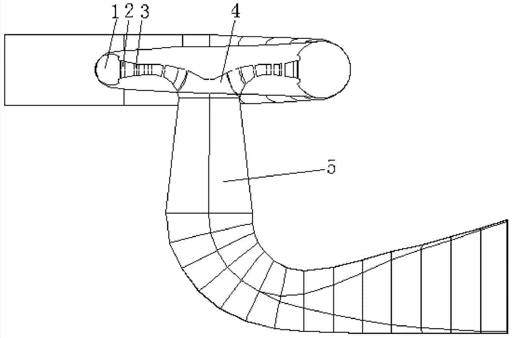
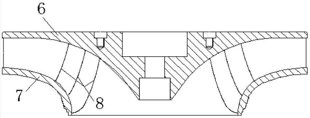
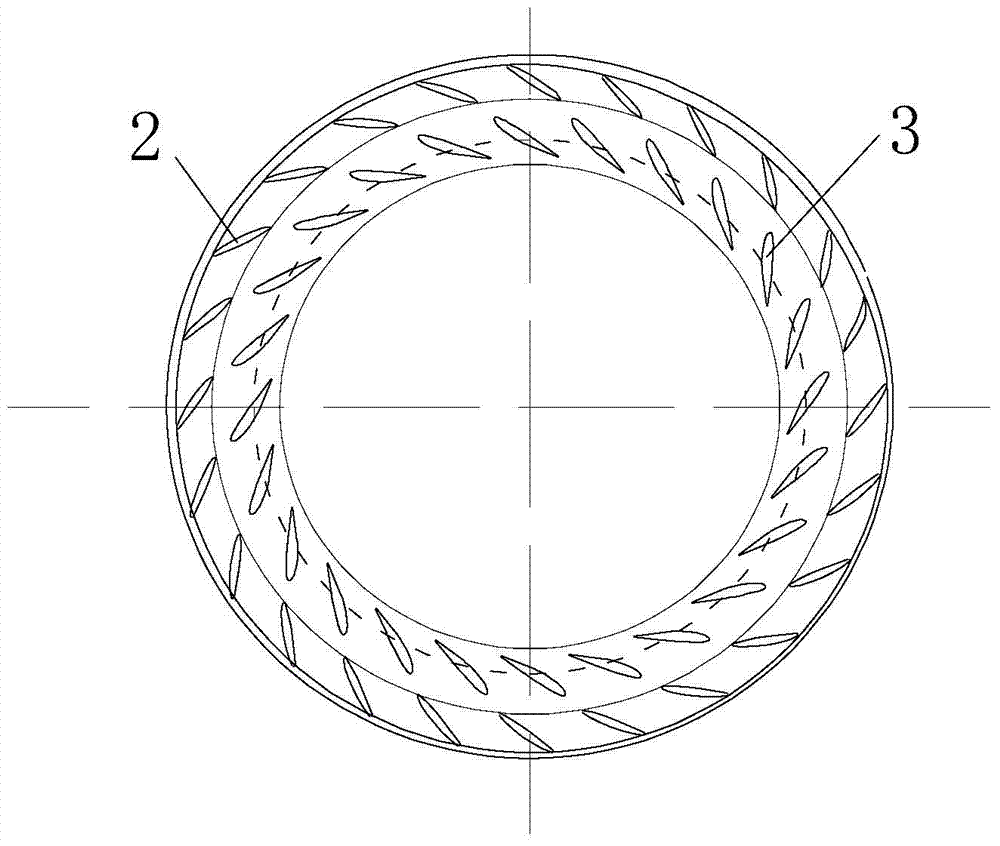
[0036] Such as Figure 1-8 As shown, it is a Francis water pump turbine of the present invention, including a volute 1, a fixed guide vane 2, a movable guide vane 3, a runner 4 and a draft tube 5, the runner 4 is located in the middle of the volute 1, and the fixed guide vane 2 and movable guide vanes 3 are distributed in the volute 1 close to the runner 4, the draft tube 5 is connected to the middle of the bottom surface of the volute 1, the runner 5 is mainly composed of the upper crown 6, the lower ring 7 and the blade 8, and the blade 8 is located on the upper crown Between 6 and the lower ring 7, the blades 8 are distributed in groups along the circumference of the lower ring 7. In this embodiment, there are 5 groups of blades, and each group of blades consists of a long blade 9, a medium-long blade 10 and two short blades 11. , one of the short blades is located between the long blades 9 and the middle and long blades 10 as the first short blade 12 , and the other short ...


PUM


Abstract

The invention discloses a mixed-flow type water pump turbine. The mixed-flow type water pump turbine comprises a volute, fixed guide vanes, movable guide vanes, a turning wheel and an exhaust water pipe, wherein the turning wheel is located at the middle part inside the volute; the fixed guide vanes and the movable guide vanes are distributed inside the volute and are located near the turning wheel; the exhaust water pipe is connected to the middle part of the bottom of the volute; the turning wheel is mainly composed of an upper canopy, a lower ring and vanes; the vanes are located between the upper canopy and the lower ring and are distributed along the circumference of the lower ring in groups; each group of the vanes is composed of a long vane, an intermediate van and two short vanes; one short vane serves as a first short vane and is located between the long vane and the intermediate vane of the group of the vanes while the other short vane serves as a second short vane and is located between the intermediate vane of the group of the vanes and the long vane of the adjacent group of the vanes. The bending degree of the curve in an S region is reduced obviously, the secondary flow loss is lower, the flowing property of a flow field is improved, the running stability of a machine set is guaranteed, and the likelihood of occurrence of vibration of the machine set is reduced.

Description

technical field [0001] The invention relates to a water pump turbine, in particular to a mixed flow water pump turbine. Background technique [0002] The pumped storage power station is a hydropower station that uses the electricity when the load in the power grid is low, pumps water from the lower reservoir to the upper reservoir for energy storage, and releases water back to the lower reservoir for power generation when the power grid is at peak load. It can not only adjust peak, frequency, and phase, but also undertake emergency backup to ensure the safe and stable operation of the power grid, and at the same time, it can improve the energy structure and alleviate water consumption conflicts. [0003] At present, with the rapid development of economy and society, the requirements for pumped storage power stations are getting higher and higher. As the core components of power station units, pumped storage units are extremely important for their safe, stable and efficient o...

Claims


Application Information

Patent Timeline
Patent Type & Authority Applications(China)
IPC IPC(8): F03B3/12
CPCY02E10/223Y02E10/20
Inventor 姚泽王正伟阎宗国支发林黄青松杨静徐广文李玺
Owner ELECTRIC POWER RES INST OF GUANGDONG POWER GRID
Why Eureka
Try Eureka