Phase change material thermal buffering device and method for dissipating heat of high-power device

A phase-change material and high-power technology, applied in electric solid devices, semiconductor devices, semiconductor/solid-state device components, etc., can solve the problems of high heat flux density, low operating temperature, small size, etc. Improve thermal conductivity and save space

Active Publication Date: 2014-04-02
BEIJING AEROSPACE TIMES OPTICAL ELECTRONICS TECH
View PDF3 Cites 7 Cited by
  • Summary
  • Abstract
  • Description
  • Claims
  • Application Information

AI Technical Summary

Problems solved by technology

[0006] The technical problem solved by the present invention is: for optoelectronic devices with high thermal power and low working temperature, small volume and high heat flux density, a new thermal buffer me

Method used


Image

  • Phase change material thermal buffering device and method for dissipating heat of high-power device
  • Phase change material thermal buffering device and method for dissipating heat of high-power device
  • Phase change material thermal buffering device and method for dissipating heat of high-power device

Examples


Embodiment Construction

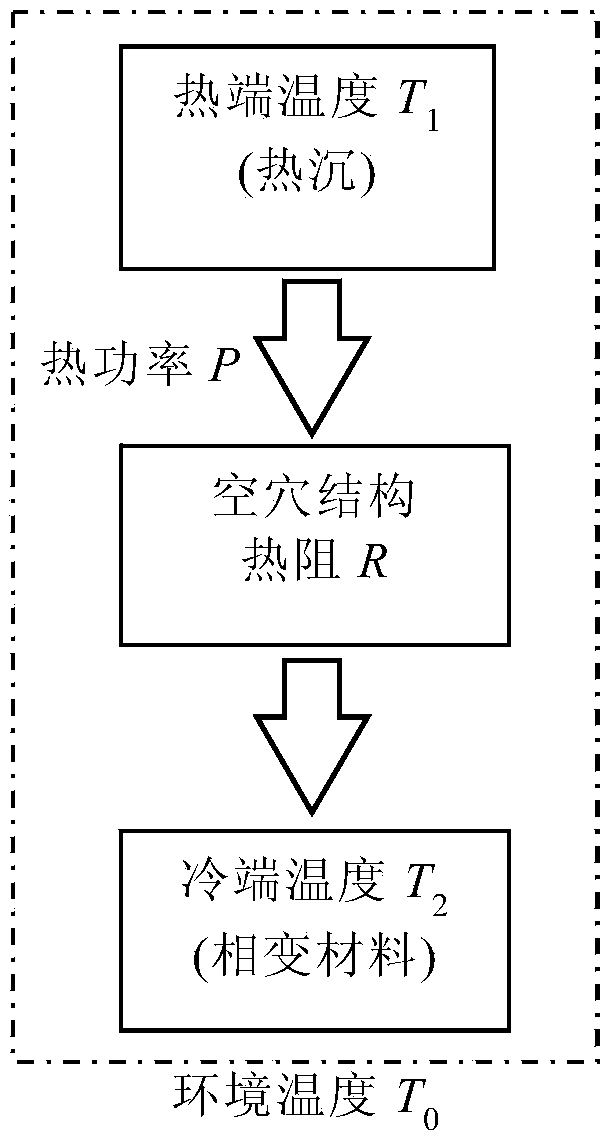
[0024] The method and device for thermal buffering of phase change materials according to the present invention will be described in detail below in conjunction with specific embodiments. Multiple LD pump sources of high-power lasers generate 2500W thermal power and work continuously for 3 minutes. The uniform arrangement of all LDs results in uniform heating of the circular heat sink with a diameter of 400 mm. The working temperature of LD is 20~30℃, and the working environment temperature is 0℃. It is required to keep the LD temperature within the normal working range within 3 minutes, and the total height of the thermal buffer device of the equipment should not exceed 40mm.

[0025] The heat P generated by the high-power laser is 2500W, and the working time t is 3min. The thermal power is too high, both air cooling and water cooling methods are difficult to export in time, a large amount of heat energy accumulated in the thermal diffusion device causes the LD temperature ...


PUM


Abstract

The invention discloses a phase change material thermal buffering device and method for dissipating heat of a high-power device. A phase change material is taken as a heat conduction cold end T2 since the phase change material has the characteristic of constant phase change heat absorption temperature, a certain temperature difference is formed between the heat conduction cold end T2 and a heat sink T1 of equipment, heat dissipated by a heat-end device is introduced into a phase change energy-storing substance in time, and the temperature T1 of the device is kept within an allowed working temperature range in the working time t of the heat-end device. The phase change material thermal buffering device consists of a heat sink, a honeycomb structure etched at the bottom of the heat sink, and a phase change material filled into honeycomb cavities. The effectiveness of the phase change material thermal buffering device can be evaluated via the temperature distribution of the device after the working time t under thermal power P or adjusted according to a calculation result. Temperature indexing can be obtained via an established thermal buffering process model or calculating with a finite element algorithm. By adopting the buffering device and the buffering method, the heat conduction area is increased, and the heat conduction efficiency is increased. Moreover, the heat sink and the thermal buffering device are integrated, so that the space is saved.

Description

technical field [0001] The invention relates to a high-power device, that is, a device that generates large heat power and requires low working temperature during operation, and uses a phase-change material for thermal buffering device and method. Background technique [0002] With the rapid development of optoelectronic technology, various high-power optoelectronic devices are gradually applied to various devices. However, high-power optoelectronic devices often generate a lot of heat and require a relatively low normal operating temperature. Traditionally, air cooling or water cooling is used to dissipate heat in real time. Water-cooling heat dissipation requires additional large-volume water-cooling equipment, and the water-cooling method itself has a heat dissipation limit; while the air-cooling heat dissipation limit is only one-tenth of water cooling, and the thermal power of a hundred watts cannot be removed in time. Especially for optoelectronic devices with small ...

Claims


Application Information

Patent Timeline
IPC IPC(8): H01L23/427H05K7/20
Inventor 向政王国栋宋伟马建立尹宜勇何哲玺于淼
Owner BEIJING AEROSPACE TIMES OPTICAL ELECTRONICS TECH
Why Eureka
Try Eureka