Variable valve timing and direct-injection gasoline engine cam shaft

A valve timing and camshaft technology, applied in the direction of engine components, machines/engines, mechanical equipment, etc., can solve problems such as insufficient space for camshaft layout, complex manufacturing process of camshaft, and difficulty in ensuring structural strength, and achieve structural strength Difficult to guarantee, simple structure and process, and convenient processing

Inactive Publication Date: 2014-04-09
CHONGQING CHANGAN AUTOMOBILE CO LTD
View PDF4 Cites 4 Cited by
  • Summary
  • Abstract
  • Description
  • Claims
  • Application Information

AI Technical Summary

Problems solved by technology

Engine development requires comprehensive use of the above new technologies. The camshaft needs to be equipped with a variable valve timing control oil circuit and a high-pressure oil pump drive cam, especially for compact and small displacement engines. The layout space of the camshaft is insufficient and the structural strength is insufficient. Difficult to guarantee
[0003] When designing the variable valve timing control oil circuit on the camshaft, in order to ensure the oil flow, the oil holes can be made larger or the number increased, but the strength of the camshaft journal must also be considered. Only increasing the camshaft journal will inevitably cause The manufacturing process of the camshaft is complicated, the space arrangement is difficult and the weight increases
[0004] When the high-pressure oil pump drive cam is designed on the camshaft, it is arranged in the middle section of the camshaft, which will increase the overall height of the engine and limit the overall layout of the engine
Moreover, for naturally aspirated engines, key parts such as cylinder heads and cylinder head covers need to be changed, reducing the commonality of parts

Method used


Image

  • Variable valve timing and direct-injection gasoline engine cam shaft
  • Variable valve timing and direct-injection gasoline engine cam shaft
  • Variable valve timing and direct-injection gasoline engine cam shaft

Examples


Embodiment Construction

[0019] Further illustrate structure of the present invention below in conjunction with accompanying drawing:

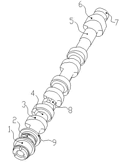
[0020] Such as figure 1 The camshaft shown includes: first, second, third, fourth and fifth camshaft journals 1, 2, 4, 5, 7, ventilation cam 3, oil pump drive cam 6, outer hexagonal structure 8 And annular boss 9.

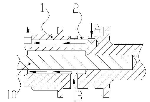
[0021] Among them, the first section of camshaft journal 1 is at the front end of the camshaft, and is closely matched with the phaser during assembly to seal the local oil passage at the front end of the camshaft.

[0022] The second section of camshaft journal 2 is arranged behind the first section of camshaft journal 1, and is processed with annular oil grooves and radial oil holes required for variable valve timing. Both sides of the neck are respectively provided with annular bosses 9, which are used to limit the axial movement of the camshaft.

[0023] There are 3 pairs of ventilation cams 3, separated by a certain distance, and evenly arranged at...


PUM


Abstract

A variable valve timing and direct-injection gasoline engine cam shaft comprises a variable valve timing oilway, three pairs of air change cams and a high-pressure oil pump drive cam. The variable valve timing oilway is arranged on the first section and the second section cam shaft journals close to the front end of the cam shaft and comprises a phase advance oilway and a phase lag oilway. The air change cams are arranged on the middle section of the cam shaft at certain intervals. The included angle among the air change cams evenly distributed is 120 degrees. The high-pressure oil pump drive cam is disposed at the rear end of the cam shaft, three tips are evenly disposed on the cam, and the width of the cam is larger than that of each aeration cam. The variable valve timing and direct-injection gasoline engine cam shaft is reasonable and simple in structure and convenient to machine, the problems that the arranging space of the cam shaft is insufficient and the structural strength of the cam shaft cannot be guaranteed are solved, large modification on key parts such as a cylinder head and a cylinder head cover is not needed, part universality is increased, and the cam shaft is quite applicable to small-displacement engines with compact structures.

Description

technical field [0001] The invention relates to a gasoline engine camshaft, in particular to a camshaft used for variable valve timing and in-cylinder direct injection engines. Background technique [0002] Variable valve timing technology is to change the opening and closing time of the valve through electronic control technology, improve the intake efficiency of the engine in certain speed ranges, thereby increasing the engine torque and power. Direct injection technology is to use the principle of lean gas combustion to directly spray high-pressure gasoline into the cylinder in the form of mist for combustion. The extremely high fuel pressure and cylinder pressure ensure the lean gas, which will greatly improve the economy and power of the engine. Engine development requires comprehensive use of the above new technologies. The camshaft needs to be equipped with a variable valve timing control oil circuit and a high-pressure oil pump drive cam, especially for compact and s...

Claims


Application Information

Patent Timeline
Patent Type & Authority Applications(China)
IPC IPC(8): F01L1/047F02M59/10
Inventor 张云富李春何海珠余训蒋树徽朱玉明
Owner CHONGQING CHANGAN AUTOMOBILE CO LTD
Why Eureka
Try Eureka