
Micro CMOS power amplifier

A technology of power amplifiers and amplifying circuits, which is applied in the direction of power amplifiers, amplifiers, improved amplifiers to improve efficiency, etc., and can solve problems such as transformer power loss

Inactive Publication Date: 2014-04-09
INKTEC CO LTD
View PDF0 Cites 0 Cited by
  • Summary
  • Abstract
  • Description
  • Claims
  • Application Information

AI Technical Summary

Problems solved by technology

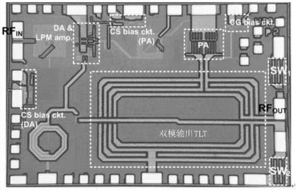
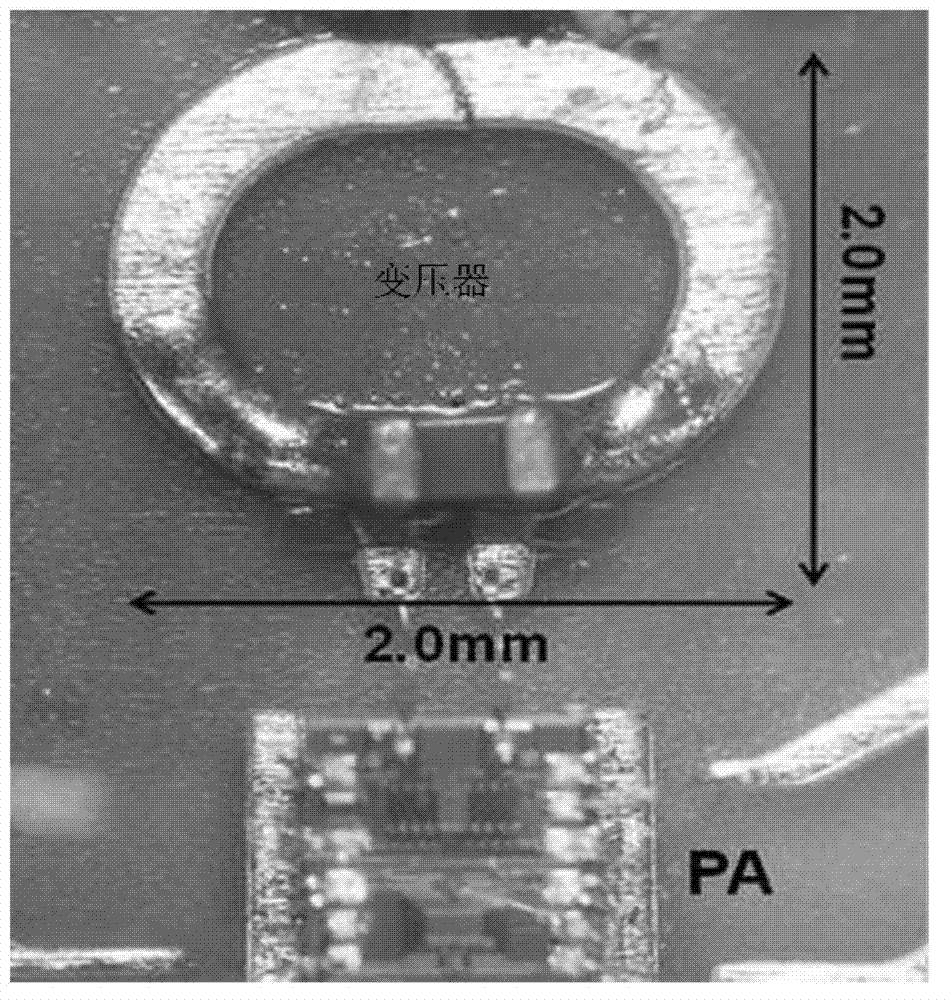
[0016] However, as mentioned above, in order to increase the output of the CMOS power amplifier, the configuration of the transformer is essential, but the transformer generates power loss depending on the structure and material, and accounts for nearly 50% of the entire chip size of the power amplifier. Therefore, it has become a stumbling block to common use

Method used


Image

  • Micro CMOS power amplifier
  • Micro CMOS power amplifier
  • Micro CMOS power amplifier

Examples


Embodiment Construction

[0037] Hereinafter, specific contents for implementing the present invention will be described with reference to the drawings.

[0038] In addition, in description of this invention, the same code|symbol is attached|subjected to the same part, and the repeated description is abbreviate|omitted.

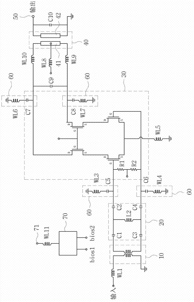
[0039] First, refer to figure 2 The circuit configuration of the micro CMOS power amplifier according to the first embodiment of the present invention will be described.

[0040] Such as figure 2 As shown, the circuit 1 of the micro CMOS power amplifier is composed of an input circuit 10 , a matching circuit 20 , a cascode circuit 30 and an output transformer circuit 40 . Furthermore, the capacitor portion of each partial circuit is also configured by including a harmonic tuning circuit 60 for canceling vibration, heat generation, etc. of the capacitor.

[0041]The input circuit 10 is a circuit for inputting a signal, and is composed of an input balun transformer (input balun tra...


PUM


Abstract

The present invention relates to a micro CMOS power amplifier, in which an output transformer is configured as a substrate of a multilayer structure, and an amplifier circuit module is stacked on the output transformer. The micro CMOS power amplifier includes: an amplifier circuit module chip configured by modularizing circuits for amplifying power as a module; and an output transformer for outputting output of the amplifier circuit module chip to outside through a transformer circuit, in which the output transformer is implemented on a multilayer substrate, and the amplifier circuit module chip and the output transformer are configured as a stack. According to the micro CMOS power amplifier of the present invention described above, an output transformer occupying a large space in a conventional power amplifier is configured as a multilayer substrate, and thus the chip size can be reduced within 50% without decreasing output power of the power amplifier.

Description

technical field [0001] The invention relates to a micro CMOS power amplifier in which an output transformer is composed of a substrate with a multilayer structure and laminated with an amplifying circuit module. Background technique [0002] In general, items required for wireless terminals include low power, low price, miniaturization, high data rate, SDR (software defined radio, supporting multi-standard functions), etc. From the aspect of power amplifier design, in order to achieve miniaturization and low price, use CMOS process instead of GaAs to reduce external SMT (surface mount) parts, and develop as much as possible to build into mainstream RF chips. At present, in the field of power amplifier (PA) research, the most controversial point is the CMOS power amplifier. [0003] CMOS power amplifiers can be realized by a single chip of RFIC (radio frequency integrated circuit), and they are also price competitive, so they can be expected to become amplifiers for future w...

Claims


Application Information

Patent Timeline
Patent Type & Authority Applications(China)
IPC IPC(8): H03F1/02H03F3/20H01L23/58
CPCH01L2223/6611H01L23/66H01L24/06H01L2924/19105H03F2200/534H01L2224/06165H03F2200/541H01L2924/19051H01L2224/04042H01L23/5225H01L28/40H01L2924/19041H01L2924/3011H01L24/48H03F3/195H01L2224/49177H01L2924/19042H01L23/5227H01L2224/49175H01L24/49H01L23/49838H01L28/10H01L2224/48227H03F3/45188H03F3/213H01L23/49827H01L2223/6655H01L2224/05554H03F2203/45464H03F2203/45538H03F2203/45594H03F2203/45606H03F2203/45611H03F2203/45621H03F2203/45641H03F2203/45704H03F2203/45712H03F2203/45731H01L2924/30111H01L2924/00014H01L2924/00H01L2224/45099H01L2224/45015H01L2924/207H03F1/02H03F3/24H05K3/46
Inventor 尹圣万朴锺振
Owner INKTEC CO LTD
Learn More