Evaporation drum of a coating machine

A technology of evaporation drum and coating machine, applied in the field of machinery, can solve the problems of difficult to guarantee the sealing of the interface, prolong the preparation time of the coating roller, and complicated the processing technology of the coating roller, and achieve high processing efficiency, short preparation time, and coating quality. Good results

Inactive Publication Date: 2017-02-01
温岭市通茂电子装备有限公司
View PDF6 Cites 0 Cited by
  • Summary
  • Abstract
  • Description
  • Claims
  • Application Information

AI Technical Summary

Problems solved by technology

[0005] But, the problem that the dual channel water-cooled coating roller that above-mentioned winding coater is used is: 1, the cooling waterway is comparatively complicated, and the cooling waterway has the longer part not to have cooling effect or the cooling effect is not obvious, for example, the first water inlet pipe, The second water inlet pipe and the water outlet pipe cause the cooling system to respond slowly, which prolongs the preparation time before the use of the coating roller and affects the processing efficiency; 2. The first water inlet pipe, the second water inlet pipe and the water outlet pipe are all set separately. Inside the shell, the inner shell has a socket relationship with the outer shell. Such a structure complicates the processing technology of the coating roller and increases the manufacturing cost. At the same time, due to the many pipeline connection structures, it is difficult to ensure the sealing of the interface.

Method used


Image

  • Evaporation drum of a coating machine

Examples


Embodiment 1

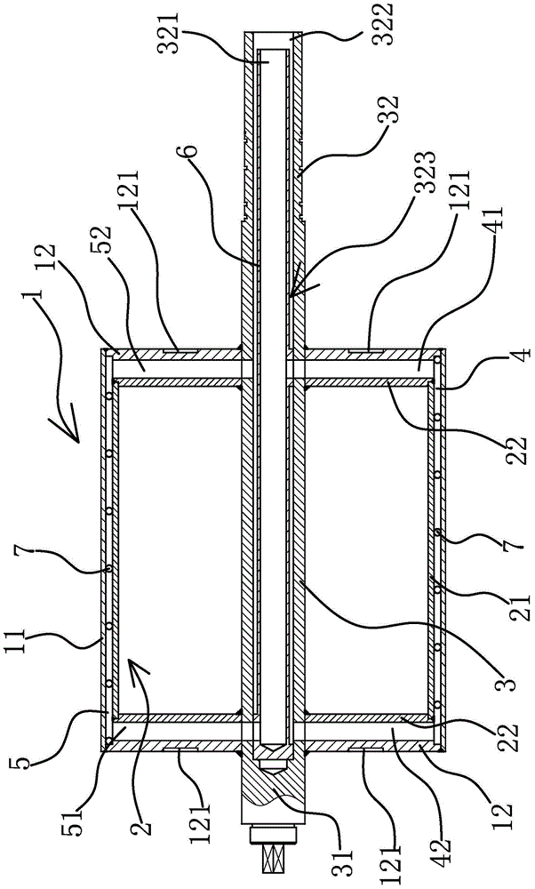
[0028] The evaporation drum of the coating machine is set on the vacuum coating machine, which is used for positioning and cooling the plastic film in the coating process. The evaporation drum of the coating machine includes an outer cylinder 1, an inner cylinder 2 and a central shaft 3.

[0029] Specifically, as figure 1 As shown, the outer cylinder 1 is sleeved on the inner cylinder 2, and a barrier member 7 is arranged between the outer cylinder 1 and the inner cylinder 2, and the barrier member 7 separates the gap between the outer cylinder 1 and the inner cylinder 2 to form a cooling channel 4 and the second cooling channel 5, the first cooling channel 4 and the second cooling channel 5 are distributed in a double-helical shape along the axial direction of the evaporation drum. In this embodiment, the barrier member 7 is round steel, which is convenient to form and easy to process. As a preferred solution, the first cooling channel 4 and the second cooling channel 5 hav...

Embodiment 2

[0035] The technical solution in this embodiment is basically the same as the technical solution in Embodiment 1. The difference lies in that in this embodiment, both the outer cylinder 1 and the inner cylinder 2 are of split structure. Specifically, the inner cylinder 2 includes an inner cylinder body 21 and inner end caps 22 located on both sides of the inner cylinder body 21. The inner side surface of the inner end cap 22 has a positioning groove 1, and the two ends of the inner cylinder body 21 are snapped into corresponding and fixedly connected with the inner end cover 22 by welding. The outer cylinder 1 includes an outer cylinder body 11 and outer end caps 12 located on both sides of the outer cylinder body 11. The end cover 12 is welded, and the inner surface of the outer end cover 12 has a second positioning groove, and the two ends of the barrier member 7 respectively abut against the second positioning groove. The dynamic balance counterweight grooves 121 are opene...

Embodiment 3

[0037] The technical solution in this embodiment is basically the same as the technical solution in Embodiment 1 or Embodiment 2. The difference lies in that in this embodiment, the barrier member 7 is a partition.


PUM


Abstract

The invention provides an evaporation drum of a coating machine and belongs to the technical field of machinery, solving the problem of poor cooling effect of the existing evaporation drum of the coating machine. The evaporation drum of the coating machine comprises an outer cylinder, an inner cylinder and a middle shaft, wherein a first cooling flow channel and a second cooling flow channel are distributed in double helix form in the axial direction of the outer cylinder; the middle shaft penetrates through the outer cylinder and the inner cylinder; the middle shaft is provided with a liquid inlet and a liquid outlet; a first liquid inlet channel and a first liquid outlet channel are formed at the two ends of the first cooling flow channel, respectively; a second liquid inlet channel and a second liquid outlet channel are formed at the two ends of the second cooling flow channel, respectively; the port of the first liquid inlet channel and the port of the second liquid outlet channel are located on the same cross section of the middle shaft; the port of the second liquid inlet channel and the port of the first liquid outlet channel are located on the same cross section of the middle shaft; the first liquid inlet channel and the second liquid inlet channel are communicated with a liquid inlet, respectively; the first liquid outlet channel and the second liquid outlet channel are communicated with a liquid outlet, respectively. The evaporation drum of the coating machine has the advantages that the cooling liquid is evener in distribution, the surface temperature of the evaporation drum is consistent and the coating quality of the plastic thin film is better.

Description

technical field [0001] The invention belongs to the technical field of machinery, and relates to a coating machine, in particular to an evaporation drum of the coating machine. Background technique [0002] Vacuum coating is a technology that forms a uniform thickness film on the surface of the material to be plated by heating the atoms of the coating material in a vacuum environment and then striking them on the material to be plated. Vacuum coating technology can be applied to aluminum coating on laser discs (CDs), metal coating on printed circuit boards, and metal or metal alloy coatings on plastic films. [0003] During the coating process of the plastic film, due to the small thickness of the plastic film, it is difficult to fix, so it is necessary to use the evaporation drum to support the plastic film to be coated. However, the small thickness of the plastic film will also cause it to be easily burned through by the atoms of the coating raw material during the coatin...

Claims


Application Information

Patent Timeline
Patent Type & Authority Patents(China)
IPC IPC(8): C23C14/24
Inventor 林正亮
Owner 温岭市通茂电子装备有限公司
Why Eureka
Try Eureka