A pulsed n×n array laser radar system

A technology of laser radar and pulse type, which is applied in the field of pulse type N×N array laser radar system, can solve the problems of complex optical system design, large amount of calculation, and low precision, so as to simplify the circuit processing system structure, improve reliability and Stability, the effect of reducing design complexity

Active Publication Date: 2016-03-02
GUILIN UNIVERSITY OF TECHNOLOGY
View PDF5 Cites 0 Cited by
  • Summary
  • Abstract
  • Description
  • Claims
  • Application Information

AI Technical Summary

Problems solved by technology

[0002]Lidar measurement is an active optical remote sensing technology that has rapidly developed into a hot spot, providing an important means for obtaining spatial three-dimensional data. Single-point scanning lidar has developed into a The main disadvantages of commercial products are: high requirements on laser repetition rate, scanning device, complex optical system design, high power consumption, and low imaging speed
[0004] The ICCD area array detector is developed based on the purpose of obtaining high-resolution two-dimensional images. The invention with the application number 200910071450.9 and "Staring Imaging Based on Area Array Detectors" of the "Optoelectronic Engineering" journal, Volume 40, Issue 2, February 2013 "LiDAR" has disclosed the research of ICCD area array detectors for non-scanning three-dimensional imaging. The disadvantage is that complex modulation and demodulation methods must be used to obtain a distance image indirectly through the fusion of multiple intensity images, and the accuracy is not high. The amount of calculation is large, and the target distance information cannot be obtained instantly, and it is limited to short-range detection of up to several hundred meters, and requires a large laser emission power
Using Damman grating to split the emitted laser evenly, although the laser emission power can be reduced, but the Damman grating is expensive
In addition, none of the above-mentioned lidar systems collects laser scattering echo intensity information and distance information synchronously.

Method used


Image

  • A pulsed n×n array laser radar system
  • A pulsed n×n array laser radar system
  • A pulsed n×n array laser radar system

Examples


Embodiment

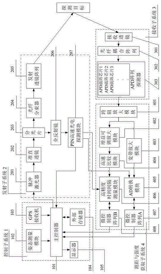
[0050] like figure 1 As shown, a pulsed N×N array laser radar system in this embodiment is composed of a control subsystem 1 , a transmitting subsystem 2 , a receiving subsystem 3 , and a ranging and intensity acquisition subsystem 4 . The control subsystem 1 includes: a main controller 101 , an attitude measurement module 102 , a GPS receiver 103 , an external memory 104 and a display 105 . The transmitting subsystem 2 includes: a pulsed laser 201 , a collimating lens 202 , a beam splitter 203 , a fiber beam splitter 204 , a transmitting lens array 205 , a total reflection mirror 206 and a PIN high-speed photodetection module 207 . The receiving subsystem 3 includes: a receiving lens 301 , a fiber coupling array 302 and an APD array detector 303 . The ranging and intensity acquisition subsystem 4 includes: a transimpedance amplification module 401, an adjustable gain amplification module 402, a broadband amplification module 403, a high-speed comparison module 404, an AD con...


PUM


Abstract

The invention discloses a pulsed N*N array laser radar system. Including main controller, attitude measurement module, GPS receiver, external memory, display, pulse laser, collimating lens, beam splitter, optical fiber beam splitter, transmitting lens array, total reflection mirror, PIN high-speed photoelectric detection module, receiving lens, Fiber-coupled array, avalanche photodiode or APD array detector, transimpedance amplifier module, gain-adjustable amplifier module, high-speed comparison module, high-precision time interval measurement module, broadband amplifier module, analog-digital or AD conversion module, microcontroller array A and microcontroller array B. The pulse laser dot matrix of the present invention illuminates the target, and the emission power is fully utilized; the distance and intensity information are acquired synchronously instantly; the APD array detector composed of multiple APD area array chips improves the resolution; no scanning device significantly reduces the complexity of optical design; the use of optical fibers The coupling array effectively reduces ambient light and stray light outside the field of view from entering the APD array detector.

Description

technical field [0001] The invention relates to laser radar technology in the field of active optical aerial remote sensing payloads, in particular to a pulsed N×N array laser radar system. Background technique [0002] Lidar measurement is an active optical remote sensing technology that has rapidly developed into a hot spot. It provides an important means for obtaining spatial three-dimensional data. Single-point scanning lidar has developed into a commercial product. Its main disadvantages are: the laser repetition rate requirements High, requires a scanning device, complex optical system design, high power consumption, and low imaging speed. [0003] After the 1990s, developed countries began to develop area-array laser radars. The detectors mainly use two types: ICCD (enhanced charge-coupled device) and APD (avalanche photodiode). Due to the relatively weak supporting foundation of photoelectric detection materials and technological level in China, research in the fiel...

Claims


Application Information

Patent Timeline
Patent Type & Authority Patents(China)
IPC IPC(8): G01S17/02G01S17/42G01S7/481
CPCG01S7/481G01S17/02G01S17/42
Inventor 周国清周祥张飙马建军卫斌
Owner GUILIN UNIVERSITY OF TECHNOLOGY
Why Eureka
Try Eureka