Low-cost back-contact cell production method suitable for mass production

A technology of back contact battery and production method, which is applied in the direction of circuits, photovoltaic power generation, electrical components, etc., can solve the problems of complicated process steps, high equipment investment and high production cost, and achieve the effect of simple process, increased equipment investment, and reduced complex processes

Inactive Publication Date: 2014-04-23
JIANGSU SUNPORT POWER CORP LTD
View PDF6 Cites 34 Cited by
  • Summary
  • Abstract
  • Description
  • Claims
  • Application Information

AI Technical Summary

Problems solved by technology

[0005] Purpose of the invention: Aiming at the problems of complex process steps, high equipment investment and high production cost in the prior art, the present invention provides a back contact battery production method with less equipment and simple process, which is suitable for large-scale production with low cost and large production capacity need

Method used


Image

  • Low-cost back-contact cell production method suitable for mass production
  • Low-cost back-contact cell production method suitable for mass production
  • Low-cost back-contact cell production method suitable for mass production

Examples


Embodiment 1

[0032] A method for producing a back contact cell, comprising the following specific steps:

[0033] (1) Use solar-grade P-type monocrystalline or polycrystalline silicon wafers as substrates;

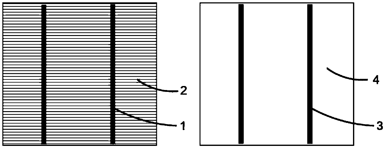
[0034] (2) According to Figure 4 The laser hole is shown, the shape of the hole is circular, and the diameter is 0.1~0.5mm; further, the laser is used to make holes on the crystalline silicon wafer, and the shape of the hole can be round, square or tapered, etc. 1mm, the number and distribution of holes are not limited to Figure 4 shown;

[0035] (3) Cleaning and texturing using conventional chemical cleaning and texturing methods;

[0036] (4) Use POCl3 diffusion source for high-temperature back-to-back single-sided diffusion, and the diffusion resistance is controlled at 40~120Ω / □;

[0037] (5) Prepare a circular paraffin mask with a diameter of 2-8 mm on the back surface of the silicon wafer as the center of the circle, and the preparation method is inkjet printing or screen p...

Embodiment 2

[0044] A method for producing a back contact cell, comprising the following specific steps:

[0045] (1) Use solar-grade P-type monocrystalline or polycrystalline silicon wafers as substrates;

[0046] (2) According to Figure 4 The shown laser opening, the shape of the hole is circular, and the diameter is 0.1~0.5mm;

[0047] (3) Cleaning and texturing using conventional chemical cleaning and texturing methods;

[0048] (4) Use POCl3 diffusion source for high-temperature back-to-back single-sided diffusion, and the diffusion resistance is controlled at 40~120Ω / □;

[0049] (5) Use a chemical solution for chemical post-cleaning to remove the pn junction at the periphery and the back, and remove the phosphosilicate glass formed on the surface of the silicon substrate after diffusion;

[0050] (6) Evaporate SiNx anti-reflection film on the front of the cell, the refractive index is between 1.9 and 2.1, and the film thickness is 70-90nm; on the back of the cell, evaporate the A...


PUM


Abstract

The invention discloses a low-cost back-contact cell production method suitable for mass production, which is used for producing solar cells. The low-cost back-contact cell production method suitable for mass production has the advantages that since a laser process (laser boring) is adopted, conventional unilateral diffusion is adopted, special leakage protection measures are taken around holes and other processes are consistent with the processes for producing conventional cells, the process is simple, the cost of added equipment is low and the product performance and the finished product rate are superior to the existing scheme.

Description

[0001] technical field [0002] The invention relates to a production method of a back contact cell, which is applied to the production and manufacture of solar cells. Background technique [0003] like figure 1 As shown, the existing conventional solar cells have 2-4 silver busbars as positive and negative electrodes on both sides of the front and back respectively. A drop in efficiency. The back-contact solar cell uses a special design to move the silver grid on the front of the conventional battery to the back, which effectively reduces the power loss caused by the shading of the silver grid, and improves the utilization of incident sunlight and the photoelectric conversion efficiency of the battery. A relatively easy method to implement in back-contact batteries is the so-called metal perforated winding structure, which uses conductive materials to guide the current generated on the front of the battery to the back through holes. A typical example is the MWT developed ...

Claims


Application Information

Patent Timeline
Patent Type & Authority Applications(China)
IPC IPC(8): H01L31/18
CPCH01L31/022425Y02E10/50Y02P70/50
Inventor 路忠林李质磊盛雯婷张凤鸣
Owner JIANGSU SUNPORT POWER CORP LTD
Why Eureka
Try Eureka