Adjustable and controllable dye laser based on light fluid

A dye laser and optical fluid technology, which is applied in the optical field, can solve the problems of high requirements on the preparation process, complex system and difficulty, and achieve the effects of high utilization rate of pump light energy, simple preparation process and simple system structure.

Inactive Publication Date: 2014-04-23
高秀敏
View PDF6 Cites 7 Cited by
  • Summary
  • Abstract
  • Description
  • Claims
  • Application Information

AI Technical Summary

Problems solved by technology

This laser has considerable advantages, but there are still some essential deficiencies: 1) The system uses optical gratings to form feedback, and optical gratings are built in three-dimensional optical waveguides to form a distributed feedback system, and then form an optical resonant cavity, all of which are microscopic structures , which essentially makes the system have high requirements for the preparation process, the process of preparing the laser is complicated, difficult, and the whole system is complicated; 2) Once the optical microstructure in the system is formed, it cannot be changed, and the structure of the optical resonant cavity cannot be adjusted. In this way, As a result, the mode of the laser output beam cannot be adjusted, which affects the range of use of the light source and application flexibility; 3) The pumping method in the prior art is a paraxial asymmetric pump, and the side of the pump beam is irradiated into the optical gain area, and contains The region of the dye molecule affects the uniformity of the pumping effect, and the entire stimulated radiation system has asymmetry, which affects the quality of the laser output beam. At the same time, the utilization rate of the pumping light energy is low

Method used


Image

  • Adjustable and controllable dye laser based on light fluid

Examples


Embodiment Construction

[0017] The present invention will be described in further detail below in conjunction with the accompanying drawings.

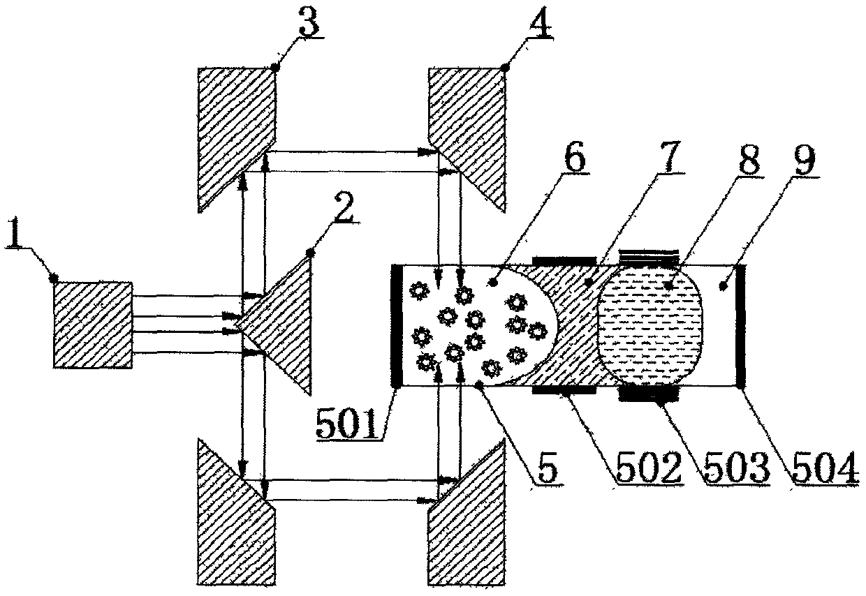
[0018] figure 1 It is a structural schematic diagram of an embodiment of the present invention. A controllable dye laser based on optofluid, in which a first conical inner reflector 3, a conical outer reflector 2, and a second conical inner reflector 4 are sequentially arranged in the beam emission direction of a pumping light source 1, and The included angles between the reflection surfaces of the first conical inner reflector 3 , the conical outer reflector 2 and the second conical inner reflector 4 and the optical axis of the pumping light source 1 are all 45°. The optical axis of the outgoing beam of the pumping light source 1 is provided with a conical surface external reflector 2 and a cylindrical quartz resonant cavity 5, and the resonant cavity 5 is sequentially provided with a first reflecting lens 501 along the beam exiting direction of the pumping...


PUM


Abstract

The invention discloses an adjustable and controllable dye laser based on light fluid. The adjustable and controllable dye laser comprises a pumping light source, a work medium and a resonant cavity, wherein a circular conical surface external reflector and the resonant cavity are sequentially arranged in an optical axis direction of an emergent light beam of the pumping light source, the resonant cavity is a transparent column body, in addition, a first optical reflector, a dye molecule suspension liquid region, a first liquid lens, a second liquid lens, a gas cavity and a second optical reflector are sequentially arranged in a cavity body of the resonant cavity in the optical axis direction, the dye molecule suspension liquid region is used as a work medium, a first electrode and a second electrode used for regulating and controlling the first liquid lens and the second liquid lens are arranged on the outer surface of the resonant cavity, and a first circular conical surface internal reflector and a second circular conical surface internal reflector are also arranged in a way of using an optical axis as a center symmetric axis. The adjustable and controllable dye laser based on light fluid has the advantages that the output laser mode is controllable, the light beam quality is good, the flexibility is high, and the like.

Description

technical field [0001] The present invention relates to the field of optical technology, in particular to an optofluid-based adjustable dye laser, which is mainly used for laser measurement, laser processing, laser guidance, laser medicine, spectrum technology, optical fiber communication, wireless optical communication, optical micromanipulation, It is used as a laser light source in the fields of optical microscopy, light-matter interaction, etc. Background technique [0002] A laser is a device that uses the principle of stimulated radiation to amplify or oscillate light in certain excited substances. The working principles of various lasers are basically the same. The indispensable conditions for generating laser light are particle number reversal and large gain over loss. Therefore, the essential components of the device include the excitation source and the working medium with metastable energy levels. parts. Excitation is the excitation of the working medium to an e...

Claims


Application Information

Patent Timeline
Patent Type & Authority Applications(China)
IPC IPC(8): H01S3/20H01S3/10
Inventor 高秀敏姜利平
Owner 高秀敏
Why Eureka
Try Eureka