
Intelligent monitoring device of motor

An intelligent monitoring and intelligent technology, applied in the direction of emergency protection circuit devices, electrical components, etc., can solve the problems of high cost, poor effect, cumbersome debugging, etc.

Active Publication Date: 2014-04-23
工泰电器有限公司
View PDF7 Cites 4 Cited by
  • Summary
  • Abstract
  • Description
  • Claims
  • Application Information

AI Technical Summary

Problems solved by technology

[0002] At present, the existing motor intelligent monitoring device has a variety of main shell structures, some of which are separate or conjoined with the current transformer, but most of them are large in size and complex in structure, which do not meet the needs of new products; multi-channel current Most of the zero-sequence voltage measurement amplifier circuits use relatively complex multi-channel isolated current measurement amplifier circuits, multi-channel isolated voltage measurement amplifier circuits and zero-sequence measurement amplifier circuits. It is beneficial to shrink the housing; the analog output circuit used to use existing integrated module products, which had disadvantages such as high cost and poor effect; most of the display decoding circuits used relatively complex liquid crystal displays, which had many components, cumbersome debugging, and high cost; In the past, thermal memory protection was realized by single-chip software programming in the intelligent motor monitoring device. The disadvantage is that there is no memory when the power is turned off, and it cannot effectively protect the motor with excessively high temperature rise. Difficult to achieve
There are disadvantages such as poor effect, not suitable for motor intelligent protection system

Method used


Image

  • Intelligent monitoring device of motor
  • Intelligent monitoring device of motor
  • Intelligent monitoring device of motor

Examples


Embodiment Construction

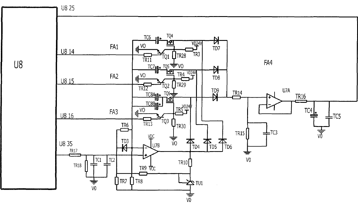
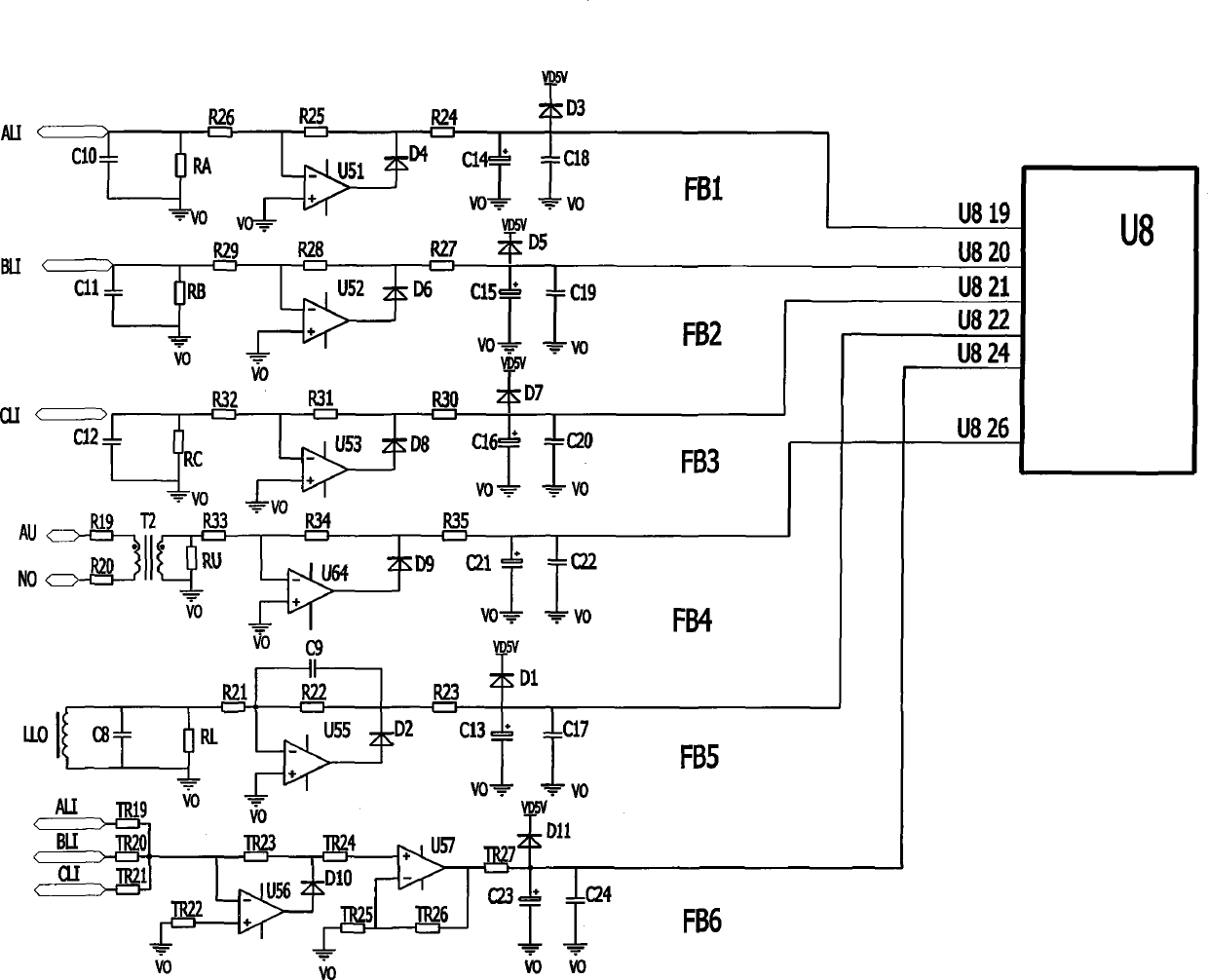
[0025] figure 1 It is the schematic diagram of the protection circuit with multiple optional thermal memory characteristics of motor intelligence. The protection circuit with multiple optional thermal memory characteristics of motor intelligence is an analog memory circuit of three sets of different data, which is combined into a thermal memory circuit with multiple characteristics by single-chip software control. The implementation mode is that the A-phase current transformer signal ALI is connected to the capacitor C10, the signal resistor RA and the resistor R26, the other end of the resistor 26 is connected to R25 and the negative input terminal of the operational amplifier U51, the positive input terminal of the operational amplifier U51 is connected to the common terminal V0, and the output of the operational amplifier U51 is One end is connected to the positive pole of diode D4, the other end of resistor R25 is connected to the negative pole of diode D4 and resistor R24,...


PUM


Abstract

The invention relates to an intelligent monitoring device of a motor. The intelligent monitoring device of the motor is characterized in that a simulation thermal memory analog protection circuit of the motor is combined with an intelligent digital control circuit to respectively form three simulation analog memory circuits of different data, i.e. a simulation analog memory circuit FA1, a simulation analog memory circuit FA2 and a simulation analog memory circuit FA3, single-chip microcomputer software is used for controlling the combination and a proper thermal memory protection curve can be automatically selected according to protection characteristics of motors with different power. A multi-channel current zero-sequence voltage measurement and amplification circuit is an AC / DC (Alternating-Current to Direct-Current) single-power-supply half-wave rectification and amplification circuit which is universally used by a current multi-channel amplification circuit, a voltage amplification circuit and a zero-sequence amplification circuit and is used for converting alternating-current signals into direct-current signals, a panel can be fixed through two methods, i.e. fixing clamps or top fixing clamps, a main case is small, the displayed characters are large by adopting four-digit LED (Light Emitting Diode) nixie tubes, the overall cost is decreased, the structure is reasonable and the intelligent monitoring device of the motor is convenient to use.

Description

technical field [0001] The invention relates to a motor intelligent protection system, in particular to a motor intelligent monitoring device. Background technique [0002] At present, the existing motor intelligent monitoring device has a variety of main shell structures, some of which are separate or conjoined with the current transformer, but most of them are large in size and complex in structure, which do not meet the needs of new products; multi-channel current Most of the zero-sequence voltage measurement amplifier circuits use relatively complex multi-channel isolated current measurement amplifier circuits, multi-channel isolated voltage measurement amplifier circuits and zero-sequence measurement amplifier circuits. It is beneficial to shrink the housing; the analog output circuit used to use existing integrated module products, which had disadvantages such as high cost and poor effect; most of the display decoding circuits used relatively complex liquid crystal dis...

Claims


Application Information

Patent Timeline
IPC IPC(8): H02H7/08
Inventor 蔡甫寒金北武杨立
Owner 工泰电器有限公司
Learn More