Technology for flue gas denitration by magnesium sulfite

A magnesium sulfite and denitrification technology, which is applied in the field of magnesium sulfite flue gas denitration process, can solve the problems of fast consumption of sulfite, high cost, and limitations, and achieve the effect of harmless treatment and high absorption efficiency

Inactive Publication Date: 2014-04-30
ZHEJIANG TIANLAN ENVIRONMENTAL PROTECTION TECH
View PDF12 Cites 11 Cited by
  • Summary
  • Abstract
  • Description
  • Claims
  • Application Information

AI Technical Summary

Problems solved by technology
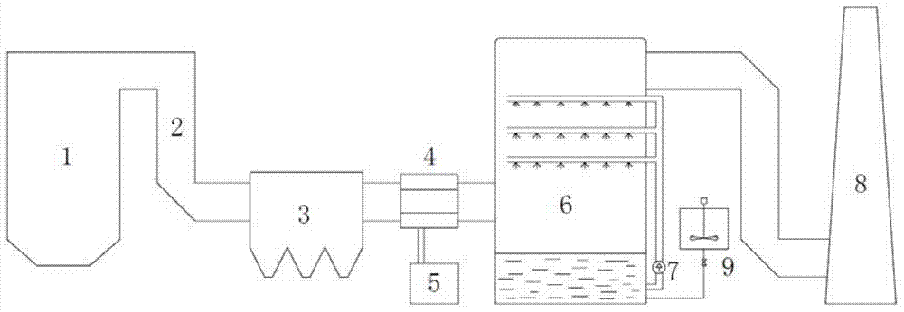
However, in this process, the photocatalytic oxidation of NO technology is still immature, and the current application and promotion will be limited, and the consumption rate of sulfite is relatively fast. If...

Method used


Image

  • Technology for flue gas denitration by magnesium sulfite

Examples


Embodiment 1

[0047] With device and process of the present invention, at 5m 3 The flue gas denitrification process is simulated on the experimental simulation device of / h scale. Flue gas volume 5m 3 / h, the flue gas composition is as follows: O 2 5%, NO is 200ppm, the rest is nitrogen, the flue gas temperature is 150 degrees Celsius, and the pressure is 1 atmosphere.

[0048]It is absorbed by spraying device, the number of spraying layers is six, and the liquid-gas ratio is 5L / m 3 , the pH is controlled at 5. Using 10% gypsum slurry for absorption, the denitrification rate is 10-15%. If the ozone is in the molar ratio O 3 : The proportion of NO = 1.1 is injected, after fully mixed and oxidized, the oxidation rate of NO at the outlet can reach 90%, and finally 5% MgSO is used 3 Slurry absorption, add 0.1% Na 2 S 2 o 3 As an oxidation inhibitor, the denitrification efficiency can reach more than 85%.

Embodiment 2

[0050] With device and process of the present invention, at 5m 3 The flue gas denitrification process is simulated on the experimental simulation device of / h scale. Flue gas volume 5m 3 / h, the flue gas composition is as follows: O 2 is 10%, NO is 230ppm, and the rest is nitrogen, the flue gas temperature is 100 degrees Celsius, and the pressure is 1 atmosphere. It is absorbed by spraying device, the number of spraying layers is six, and the liquid-gas ratio is 5L / m 3 , the pH is controlled at 5. Ozone according to the molar ratio O 3 : The ratio of NO=1.2 is injected, and the oxidation rate of NO at the outlet can reach 95%. If 10% gypsum slurry is used for absorption, the denitrification rate is 40%; if 5% MgSO is used 3 Slurry absorption, add 0.5% Na 2 S 2 o 3 As an oxidation inhibitor, the denitrification efficiency can reach more than 85%.

Embodiment 3

[0052] With the device and process of the present invention, the flue gas flow rate is 6000Nm 3 / h, the flue gas composition is as follows: O 2 is 9%, NO is 250ppm, and the rest is nitrogen, the flue gas temperature is 100 degrees Celsius, and the pressure is 1 atmosphere. It is absorbed by spraying device, the number of spraying layers is six, and the liquid-gas ratio is 5L / m 3 , the pH is controlled at 6. Ozone according to the molar ratio O 3 : The proportion of NO = 1.2 is injected, and the oxidation rate of NO at the outlet can reach 95%. If 10% gypsum slurry is used for absorption, the denitrification rate is 45%; if 10% MgSO is used 3 Slurry absorption, adding 0.5% dibutylphenol as an oxidation inhibitor, the denitrification efficiency can reach more than 85%.


PUM


Abstract

The invention discloses a technology for flue gas denitration by magnesium sulfite. The technology comprises steps of (1) after removing dust in boiler flue gas, allowing the flue gas to enter a static mixer, simultaneously spraying ozone into the static mixer, reacting the ozone and the flue gas so as to obtain mixed gas; (2) sending the mixed gas into a denitration absorption tower from the bottom of an absorption tower, adding magnesium sulfite slurry into the kettle of the denitration absorption tower, pumping the magnesium sulfite slurry into the upper part of the denitration absorption tower by a circulating pump for spraying and circulating absorption so as to denitrify the mixed gas; and (3) discharging clean denitrified flue gas by a chimney. The technology adopts sulfite for absorbing, thus maintaining the higher level of denitration performance, and realizing high efficiency of nitric oxide in flue gas.

Description

technical field [0001] The invention belongs to the technical field of environmental protection, and relates to a process for treating flue gas of coal-fired boilers, and in particular to a magnesium sulfite flue gas denitrification process. Background technique [0002] The main methods of flue gas denitrification are selective catalytic reduction technology (SCR), selective non-catalytic reduction technology (SNCR), wet complexation absorption technology, oxidation-absorption technology, etc. SCR is currently the most commonly used denitrification method. Although this technology has high denitrification efficiency, the basic investment and operating costs are expensive. In addition, this technology has poor adaptability to medium and high-sulfur coal, and the sulfur components in the flue gas can reduce the life of the catalyst, while the coal produced in China generally has a high sulfur content. Therefore, judging from my country's current national conditions, it is di...

Claims


Application Information

Patent Timeline
IPC IPC(8): B01D53/75B01D53/56
Inventor 王岳军莫建松程常杰
Owner ZHEJIANG TIANLAN ENVIRONMENTAL PROTECTION TECH
Why Eureka
Try Eureka