Gas denitration process and apparatus

a technology of denitration process and denitration apparatus, which is applied in the direction of chemistry apparatus and processes, separation processes, dispersed particle separation, etc., can solve the problem of ineffective removal of no component in the gas with a solution of any alkaline substance, and achieves high energy consumption, wide market prospects, and large ammonia consumption.

Active Publication Date: 2018-04-12
BEIJING BOYUAN HENGSHENG HIGH TECH
View PDF1 Cites 8 Cited by
  • Summary
  • Abstract
  • Description
  • Claims
  • Application Information

AI Technical Summary

Benefits of technology

[0028]At this point, the NO2-enriched denitration agent is a solution containing M(NO3)n, which is concentrated, cooled and crystallized to obtain a product of M(NO3)n, where n is a positive integer. In the denitration agents of the second type, said denitration agent is a solution composed of ethylene glycol and / or polyethylene glycol and / or water, and a denitration additive is added to the solution in order to increase the denitration ability of the denitration agent; the amount of the denitration additive is 0.5-40% by weight, preferably 2-30% by weight, more preferably 5-25% by weight, and most preferably 10-20% by weight.
[0038]The gas denitration processes of the present invention include: simple oxidation gas denitration process and oxidation gas denitration regeneration process.
[0063]Compared with the conventional SCR and SNCR, the present invention has the following advantages: (1) when the conventional SCR and SNCR processes are used for flue gas denitration, ammonia or urea is used to convert NOX in the gas to N2 and H2O at high temperatures(for SNCR, the temperature is above 850° C., and for SCR, the temperature is above 350° C., with the action of a catalyst) to achieve the purpose of denitration; however, this method has a large ammonia consumption and severe ammonia escape, resulting in the phenomenon of secondary pollution. For the gas denitration process and apparatus of the present invention, there is no phenomenon of secondary pollution, and the by-products are nitrate products of high purity, these by-products are important chemical raw materials with wide market prospects and important application values. (2) For the conventional SCR and SNCR method, ammonia is used as the denitration agent, whereas the production of ammonia itself is a process of heavy pollution and high energy consumption, which is inflammable and explosive. For the gas denitration process and apparatus of the present invention, a catalytic oxidation denitration process at room temperature is employed, safe and environmentally friendly oxidizing agents and catalysts are used without any phenomenon of secondary pollution. (3) For the gas denitration process by the conventional SCR and SNCR method, in actual applications, the effects are better at the beginning, but after a period of time, the effects of denitration decrease significantly, and the NOX content in the gas increases rapidly. For the gas denitration process and apparatus of the present invention, the purifying degree of denitration is high, and the NOX content in the gas can be reduced stably to below 30 mg / m3, while the operating cost is low, the process is short, the investment is small, and the operation is simple.

Problems solved by technology

Since NOX in a gas that has been subjected to dedusting and desulfurization is only present in the form of NO, and NO cannot be absorbed by any alkaline solution, it is impossible to effectively remove NO component in the gas with a solution of any alkaline substances.

Method used


Image

  • Gas denitration process and apparatus
  • Gas denitration process and apparatus
  • Gas denitration process and apparatus

Examples


example 1

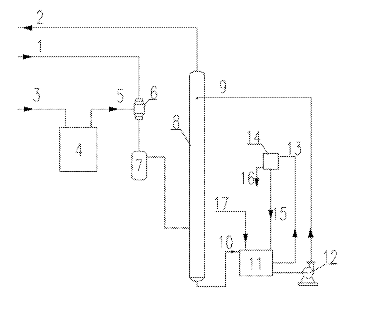
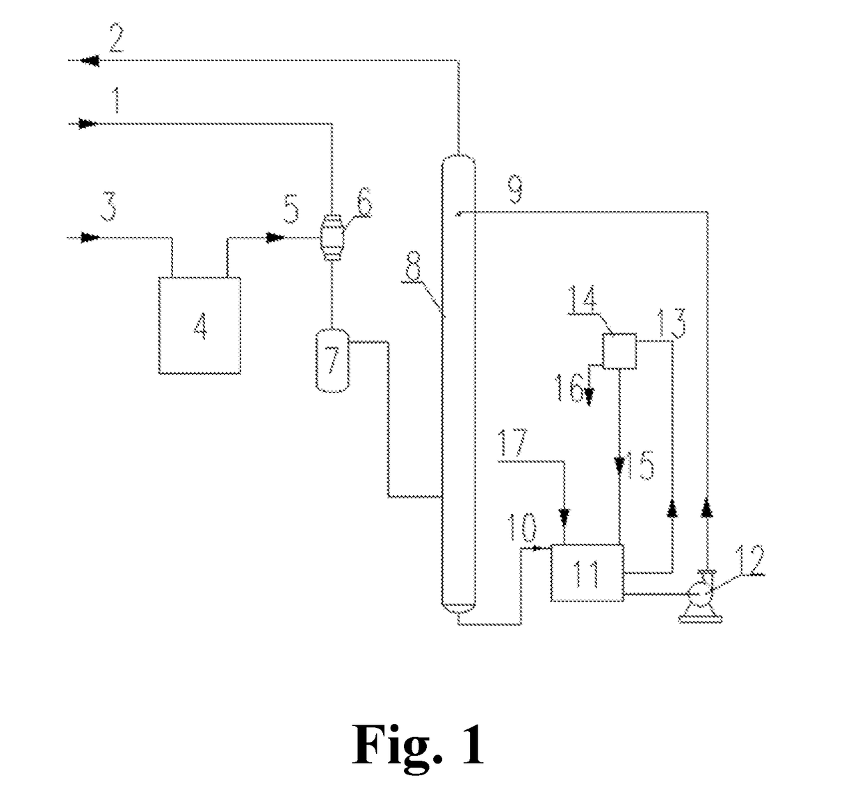
[0075]According to the denitration process and apparatus shown in FIG. 1, a set of small size simulated industrial gas denitration device was made and installed. The forms of various devices in the apparatus are as follows:

[0076]NO-containing gas 1 was a prepared cylinder gas, with a NO content of 1000-5000 ppm;

[0077]NOX content in the denitrated gas 2 was analyzed by the ultraviolet JNYQ-I-41 type gas analyzer manufactured by Xi'an Juneng Instrument Co., Ltd;

[0078]O2 gas 3 was a cylinder gas of pure oxygen;

[0079]O3 or free radical oxygen [O] generator 4 was self designed and manufactured, with an ionization area of 180 mm×240 mm, a plate gap adjustment range of 0.1-2 mm, a frequency of high frequency power supply of 5.4 MHz, an output voltage of 0-3000V and an output power of 1 KW;

[0080]O2 or O3 or free radical oxygen [O] or a mixture thereof 5 was a mixed gas of free radical oxygen [O], O3 and O2.

[0081]Mixer 6 was a glass tube filled with wire packings;

[0082]Catalytic oxidizer 7 w...
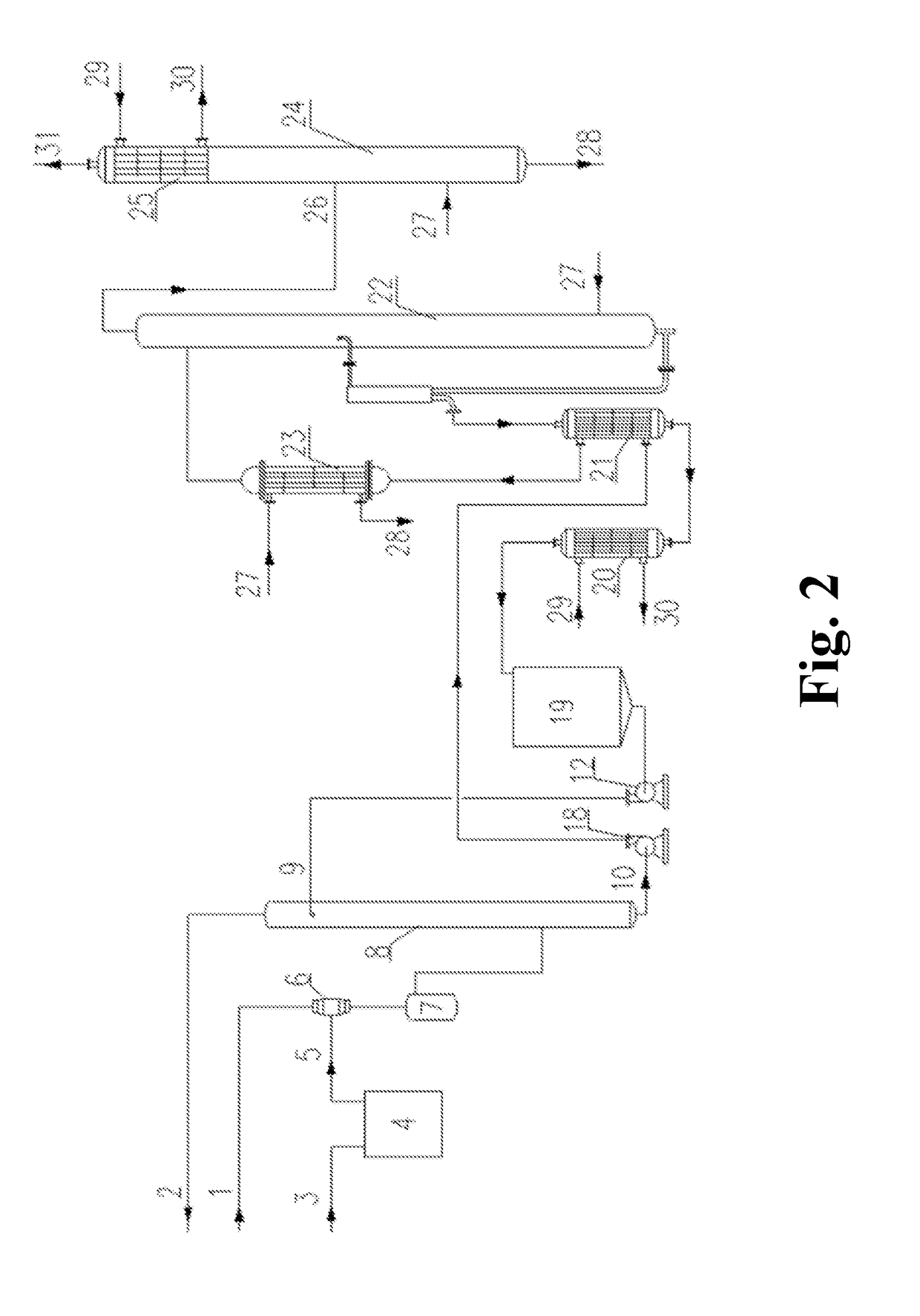
example 2

[0092]According to the process and apparatus shown in FIG. 2, a very simple denitration device was designed. With the device, the gas was allowed to pass directly through a glass absorption bottle filled with 100 mL denitration agent for absorption, and then the ultraviolet JNYQ-I-41 type gas analyzer was used to directly measure the concentration of NO in the outlet gas of the glass absorption bottle. To make the test more intuitive and simpler, a cylinder gas prepared from N2 and NO2 was used directly for the absorption test. The content of NO2 in the test cylinder gas was 5000 ppm; In the test method, a depressuring valve of the cylinder gas was directly connected to the inlet of the glass absorption bottle, then the outlet of the glass absorption bottle was directly connected to the ultraviolet JNYQ-I-41 type gas analyzer, and the gas flow rate was adjusted to 1.5 L / hr. The gas was injected into the glass absorption bottle, and recording of the absorption time was started. When ...


PUM

PropertyMeasurementUnit
temperatureaaaaaaaaaa

Abstract

A process and an apparatus for gas denitration, involving first the use of an oxidizing agent to oxidize NO in a gas to NO2, then using a denitration agent to absorb the NO2 in the gas, thus achieving the purpose of denitration.

Description

TECHNICAL FIELD[0001]The present invention relates to the industrial field of gas denitration, and particularly to a process and an apparatus for the denitration of flue gases or various combustion exhaust (waste) gases.BACKGROUND ART[0002]With the development of national economy, energy consumption increases rapidly. A large quantity of flue gases is produced by combustion of lots of fossil fuels and discharged into atmosphere, wherein besides sulfur dioxide, sulfur trioxide, hydrogen chloride, hydrogen fluoride, nitrogen oxides and a small quantity of harmful organic substances, a large quantity of dusts is contained, and there are tiny hydrophilic and non-hydrophilic particles in these dusts (mainly calcium salt particles, aluminum salt particles, magnesium salt particles, titanium salt particles, iron salt particles, lead salt particles, zinc salt particles, cobalt salt particles, rare earth element particles, radioactive element particles and particles of other harmful elements...

Claims


Application Information

Patent Timeline
Patent Type & Authority Applications(United States)
IPC IPC(8): B01D53/14B01D53/56B01D53/78B01D53/96
CPCB01D53/1487B01D53/565B01D53/78B01D53/96B01D2251/104B01D2252/10B01D2252/2026B01D53/1462B01D53/56B01D2251/10B01D2251/102B01D2251/106B01D2251/30B01D2251/40B01D2252/204B01D2252/602B01D2255/2025B01D2257/404B01D2258/0283Y02A50/20B01D53/14
Inventor WEI, XIONGHUI
Owner BEIJING BOYUAN HENGSHENG HIGH TECH
Why Eureka
Try Eureka