Shaft seal device of vertical-type low-voltage non-contact reactor

A non-contact, reactor technology, applied to the sealing of engines, engine components, mechanical equipment, etc., can solve the problems of high machining accuracy, volatile gas escape, high power consumption, etc., and achieve low maintenance rate and convenient The effect of production, reduction of wear and corrosion problems

Inactive Publication Date: 2014-04-30
XIAMEN UNIV
View PDF9 Cites 5 Cited by
  • Summary
  • Abstract
  • Description
  • Claims
  • Application Information

AI Technical Summary

Problems solved by technology

Disadvantages: high power consumption, only suitable for occasions with low pressure difference and stable flow, and also needs assistance to stop the seal
[0013] From the literature analysis of the publishe

Method used


Image

  • Shaft seal device of vertical-type low-voltage non-contact reactor
  • Shaft seal device of vertical-type low-voltage non-contact reactor
  • Shaft seal device of vertical-type low-voltage non-contact reactor

Examples


Embodiment Construction

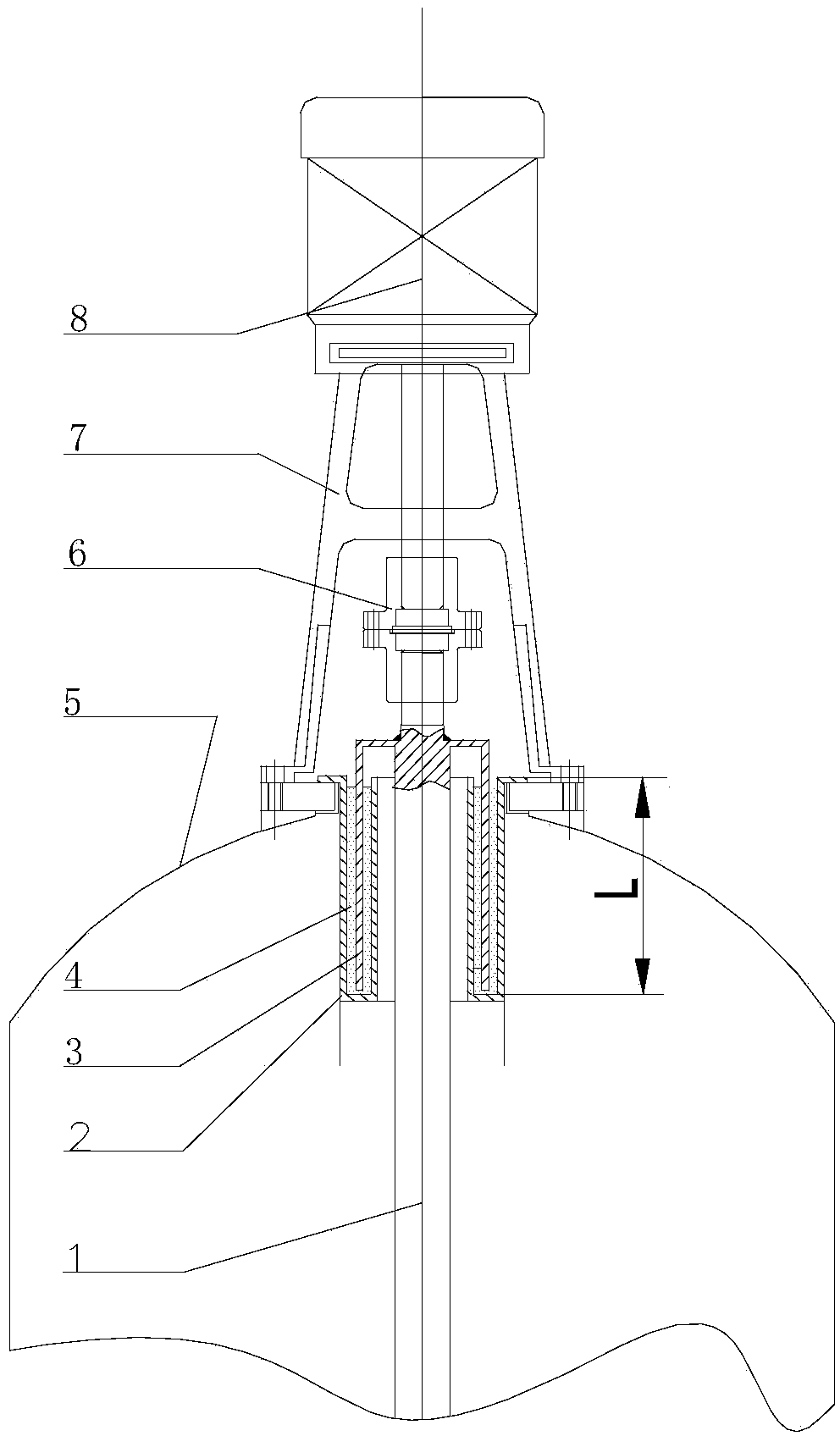
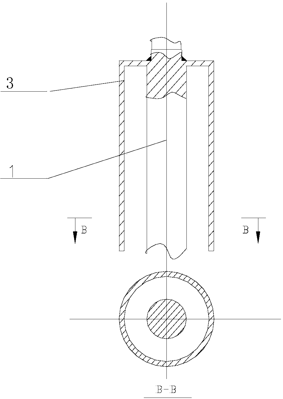
[0021] see Figure 1~3 , the embodiment of the present invention is provided with stirring shaft 1, static ring 2, moving ring 3, reactor body 5, shaft coupling 6, motor support 7, stirring motor 8; The main shaft of the motor 8 is connected, the static ring 2 is connected to the reactor body 5, the moving ring 3 is connected to the stirring shaft 1, and the sealing liquid 4 for sealing pressure is poured into the gap between the static ring 2 and the moving ring 3, The motor support 7 is located at the bottom of the stirring motor 8 .

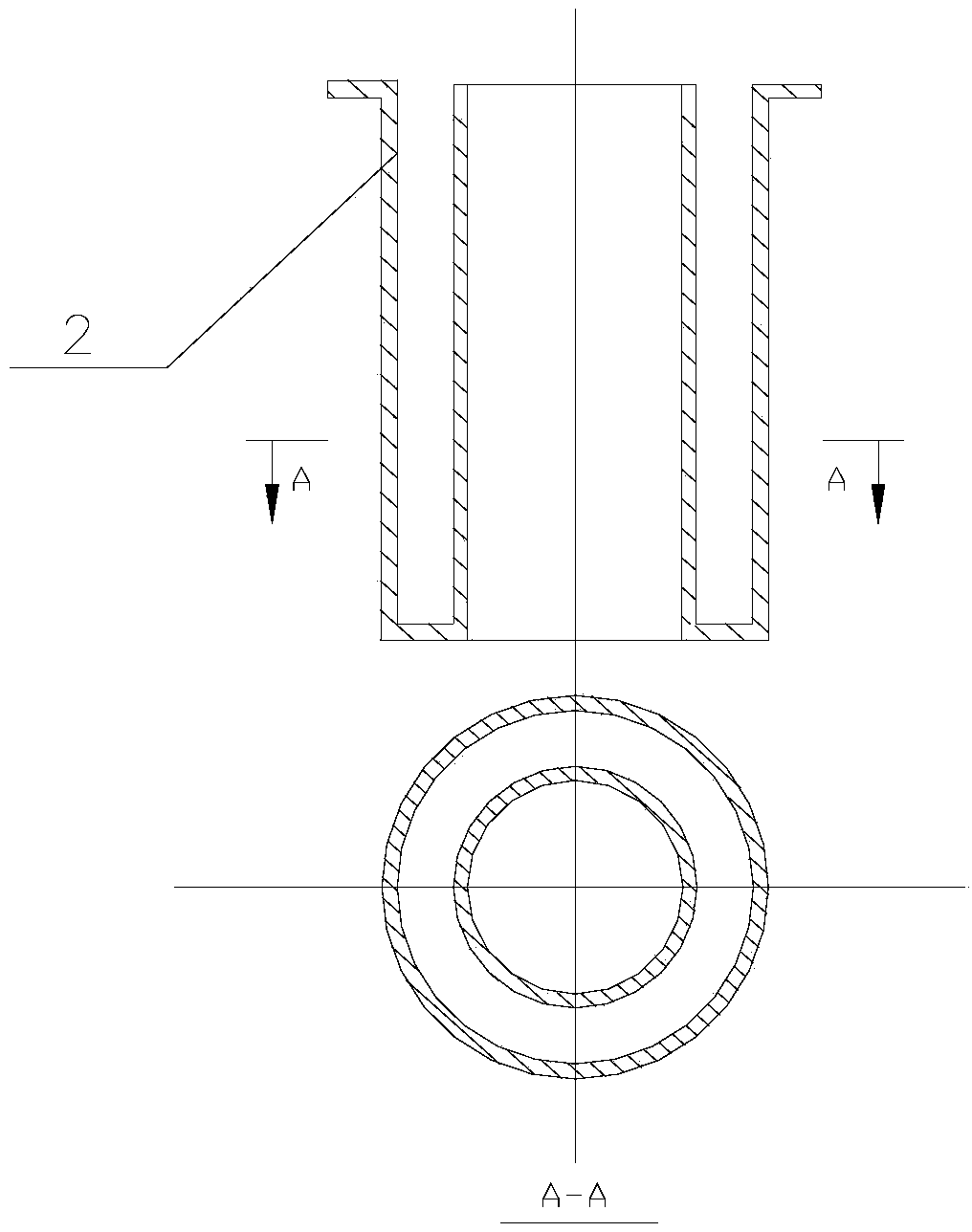
[0022] The width of the gap between the stationary ring 2 and the moving ring 3 (denoted as annular gap) may be 15-20 mm. exist figure 1 In , the mark L is the height of the static ring 2 (that is, the depth of the dynamic and static pair).

[0023] The static ring 2 is a concave groove sealing ring, and the moving ring 3 is a convex tenon sealing ring. The static ring 2 and the moving ring 3 are composed of a concave groove and a convex te...


PUM

PropertyMeasurementUnit
Gap widthaaaaaaaaaa

Abstract

The invention relates to a tank reactor, in particular to a shaft seal device of a vertical-type low-voltage non-contact reactor. The shaft seal device is provided with a stirring shaft, a static ring, a movable ring, a reactor body, a coupler, a motor support and a stirring motor. The stirring shaft is connected with a spindle of the stirring motor through the coupler, the static ring is connected with the reactor body, the movable ring is connected with the stirring shaft, gaps between the static ring and the movable ring are filled with pressure sealing liquid for pressure sealing, and the motor support is arranged at the bottom of the stirring motor. The shaft seal device is applied to the vertical-type low-pressure tank reactor; due to the adoption of the liquid pressure sealing technology, a reactor shaft seal can be less abraded and corroded by corrosive liquid and reaction materials effectively, liquid seal pressure is adjusted by changing types of shaft seal liquid and the height of injected liquid within a certain range, and wider reaction types and conditions can be suitable for. The shaft seal device has the advantages of being free of transmission and friction, simple in structure, convenient to produce and maintain, efficient, feasible and the like, is low in maintenance rate and long in service life, and liquid seal pressure can be adjusted.

Description

technical field [0001] The invention relates to a kettle-type reactor, in particular to a shaft seal device of a vertical low-pressure non-contact reactor which can effectively solve the problems of shaft seal wear and corrosion of low-pressure equipment and has excellent low-pressure sealing effect. Background technique [0002] Tank reactors are widely used in high-purity hydrometallurgy, fine chemical industry and other fields. In order to accelerate heat and mass transfer, increase reaction speed, and obtain maximum economic benefits, a mechanical stirring paddle is usually installed on the tank reactor to reduce the temperature gradient and concentration gradient in the tank reactor and speed up the reaction equilibrium . In order to prevent the leakage of volatile gas (acid mist, etc.) in the tank reactor, the mechanical stirring device uses a shaft seal to solve the dynamic and static sealing problem between the rotating stirring shaft that transmits external power i...

Claims


Application Information

Patent Timeline
IPC IPC(8): F16J15/40
Inventor 汤培平王泉游淳毅汤亦非朱丽李竞菲林康英刘碧华刘瑞聪
Owner XIAMEN UNIV
Why Eureka
Try Eureka