
Division-of-amplitude sensing design method and device for polarizing navigation angle

A polarization navigation and angle sensing technology, applied in the field of navigation and measurement and control, can solve the problems of lower measurement accuracy and sensitivity, scattering/reflection stray light interference, complex photolithography processing technology, etc., to reduce technical index requirements, improve sensitivity and Accuracy, the effect of reducing the difficulty of installation and adjustment

Inactive Publication Date: 2014-05-07
BEIJING INSTITUTE OF TECHNOLOGYGY
View PDF6 Cites 16 Cited by
  • Summary
  • Abstract
  • Description
  • Claims
  • Application Information

AI Technical Summary

Problems solved by technology

On the other hand, the ultra-precision and highly integrated photolithography processing technology is very complicated, and the cost investment is huge
In addition, due to the 2×2 pixel detection mode, the same incident light wave is divided into four parts according to the spatial position, and each pixel detects different polarization components respectively, so the utilization rate of light energy is not high, and it is easy to cause scattering / scattering between adjacent pixels. Reflected stray light interference reduces measurement accuracy and sensitivity

Method used


Image

  • Division-of-amplitude sensing design method and device for polarizing navigation angle
  • Division-of-amplitude sensing design method and device for polarizing navigation angle
  • Division-of-amplitude sensing design method and device for polarizing navigation angle

Examples


Embodiment 1

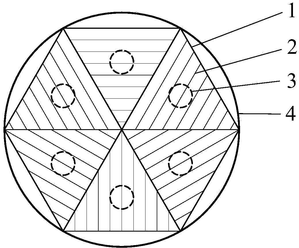
[0063] Such as Image 6 As shown, a sub-amplitude polarization navigation angle sensing device. The second phase retarder is not included in the device of this embodiment, and the first phase retarder 19 used is a half-wave plate, and the azimuth angle of the fast axis is adjusted to about 22.5°; the reference polarization generator 37 is used to generate a reference for a known polarization state Polarized light; the bandpass filter 16 is a dielectric film filter with a central wavelength of 633nm and a full width at half maximum (FWHM) of 10nm; the modulator 17 is an optical chopper, and the modulation frequency is set at 120Hz; the beam splitter 18 is a common type of light splitter Prism, the splitting ratio is about 50:50; the first polarization beam splitter 38 and the second polarization beam splitter 39 are all Wollaston prisms; photosensitive detectors 31-34 are all silicon-based amplifying detectors, and the analog voltage signals generated Passed to the data acquis...

Embodiment 2

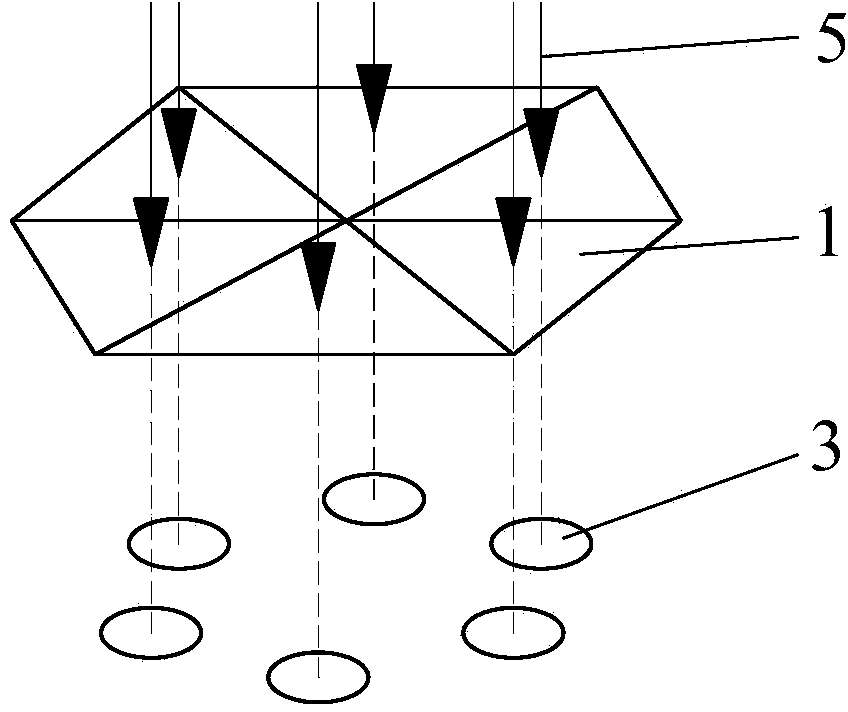
[0072] Such as Figure 10 As shown, in this embodiment, a parallel glass plate 40 is used to replace the beam splitter 18, the first polarizing beam splitting prism 38 and the second polarizing beam splitting prism 39 in Embodiment 1 for amplitude splitting, and no phase retarder is included. The upper surface of the parallel glass plate 40 is coated with a dielectric film, and the lower surface is coated with a high-reflectivity metal film. The parallel thin beams coming from the band-pass filter 16 and the modulator 17 enter the parallel glass plate 40 in an oblique incidence mode, multiple internal reflections occur in the parallel glass plate 40, and multiple times occur on the upper surface of the parallel glass plate 40 Partially transmitted, resulting in multiple parallel, equally spaced reflected beams. In this embodiment, detection is performed using the first four reflected light beams generated. The upper surface of the parallel glass plate 40 can be pressed Fig...


PUM


Abstract

The invention belongs to the fields of navigation, and measurement and control, and relates to a division-of-amplitude angle sensing design method and device for carrying out navigation by using sky scattering light polarization information. The method comprises the following steps: a) detecting an incident light polarization state by adopting a division-of-amplitude multi-channel synchronous detection method; b) achieving light-concentration and directional measurement functions by a small-field telescope; c) analyzing a vibration azimuth angle of a linear polarized electric field vector by a stokes vector and a matrix analysis method; d) carrying out system optimization design on indexes and debugging states of internal elements of a sensing device by taking an instrument matrix condition number as an evaluation factor; and e) accurately calibrating an instrument matrix of the sensing device by a benchmark polarization generator, and calibrating and accurately checking the sensing device. A new technological approach is provided for autonomous navigation by using an optical means; the method and the device can be widely applied to navigation targets of equipments such as vehicles, ships and warships, low-altitude aircrafts and autonomous robots, also can be applied to the fields such as polar research, outdoor adventure and geologic assay.

Description

technical field [0001] The invention belongs to the technical field of navigation and measurement and control, combines polarized light detection technology and navigation technology, and relates to a navigation angle sensing design method and device for navigation by using sky scattered light polarization information. It can be widely used in the navigation purposes of vehicles, ships, low-altitude aircraft, autonomous robots and other equipment, and can also be used in polar expeditions, field expeditions, geological surveys and other fields. Background technique [0002] Polarization navigation is a new navigation method that utilizes the polarization distribution pattern of scattered light in the sky for autonomous navigation. Polarization navigation was originally a bionic sensing and navigation method. It originated from the research on the polarization vision system of sand ants, bees, crickets and other insects. Through passive measurement and analysis of atmospheric...

Claims


Application Information

Patent Timeline
IPC IPC(8): G01C21/00
CPCG01C1/00G01C21/00
Inventor 张旭升赵维谦何川邱丽荣
Owner BEIJING INSTITUTE OF TECHNOLOGYGY
Learn More