Medium resonant cavity for microwave plasma lamp

A technology of dielectric resonant cavity and microwave plasma, which is applied to the parts of gas discharge lamps, discharge lamps, electrical components, etc., can solve the problems of easy bursting of dielectric resonant cavity, achieve the goal of reducing weight, increasing electric field and improving yield Effect

Inactive Publication Date: 2014-05-07
UNIV OF ELECTRONIC SCI & TECH OF CHINA
View PDF4 Cites 5 Cited by
  • Summary
  • Abstract
  • Description
  • Claims
  • Application Information

AI Technical Summary

Problems solved by technology

[0004] The purpose of the present invention is to provide a new dielectric resonant cavity structure in order

Method used


Image

  • Medium resonant cavity for microwave plasma lamp
  • Medium resonant cavity for microwave plasma lamp

Examples


Embodiment 1

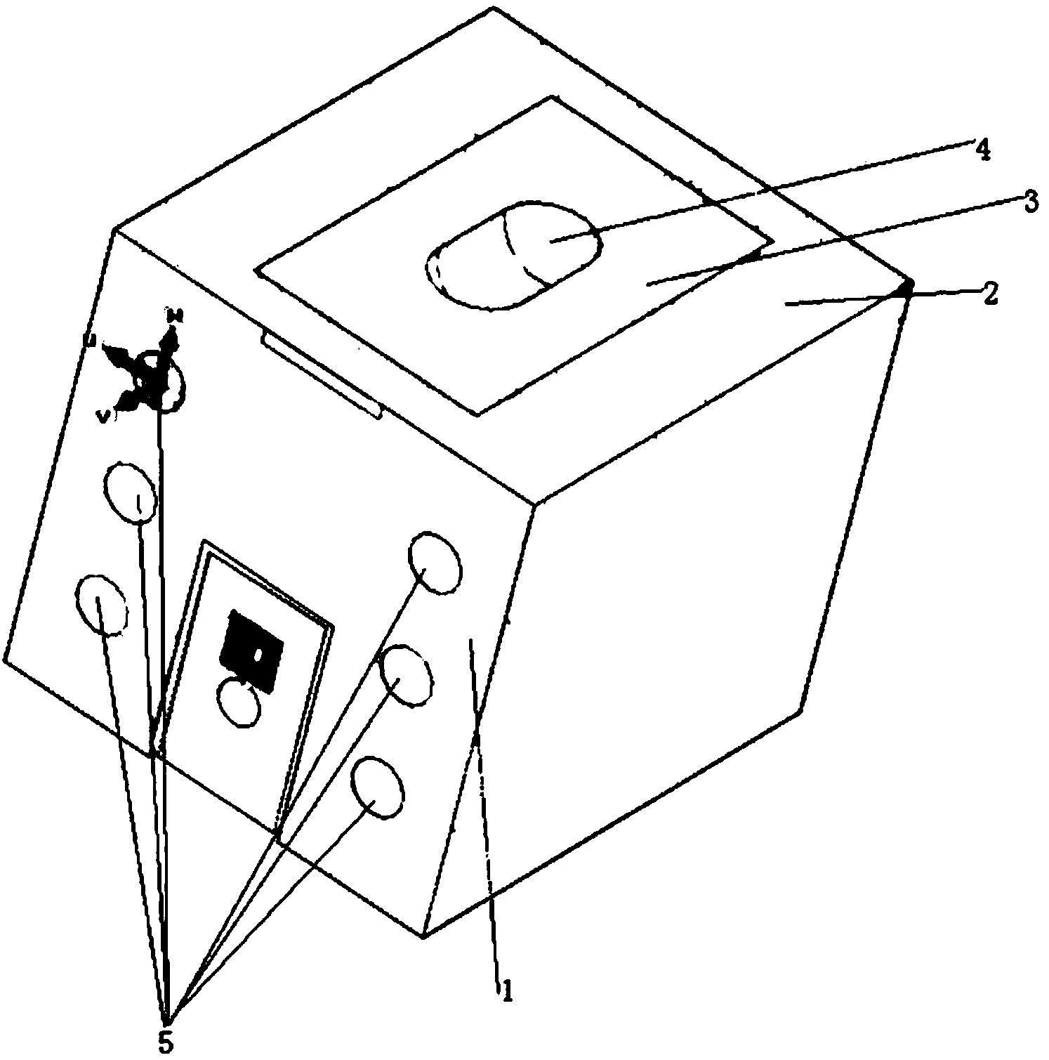
[0021] Embodiment 1: as figure 2 As shown, the hole is circular, penetrating the front and rear faces, the hole radius is 3 mm, and 3 holes are evenly arranged at both ends of the dielectric resonant cavity.

[0022] We use CST Microwave Studio to carry out full three-dimensional simulation calculations on these two structures, and find that the resonant frequency of the structure without holes is 438.4MHz, while that of the structure with holes is 440.8MHz, and the relative change rate of the resonant frequency is 0.55%. The influence of the operating frequency of the microwave plasma lamp is almost negligible.

[0023] The electric field intensity at the center of the bulb placement position is 16000V / m for the open-hole structure, and the electric field intensity for the open-hole structure is increased to 17000V / m, which is more conducive to the start-up and energy exchange of the plasma lamp.


PUM

PropertyMeasurementUnit
Resonant frequencyaaaaaaaaaa

Abstract

The invention discloses a medium resonant cavity for a microwave plasma lamp. The medium resonant cavity for the microwave plasma lamp is characterized by being provided with a punching structure which can make the medium resonant cavity not prone to burst in the machining process, and the yield of machining the medium resonant cavity is greatly improved. Meanwhile, with the punching structure, the weight of the medium resonant cavity can be reduced, and therefore the weight of the plasma lamp is reduced. Furthermore, with the punching structure, an electric field where a bulb is placed can be further enlarged, starting of the bulb and the enhancement of energy exchange are facilitated.

Description

technical field [0001] The invention belongs to the field of plasma lighting, in particular to an electrodeless plasma lamp excited by microwave radiation. Background technique [0002] The working principle of the microwave plasma lamp is: the microwave source is connected with a dielectric resonant cavity to form a radio frequency circuit, and a closed quartz bulb containing filling materials and other gases is placed in the center of the resonant cavity. The power amplifier generates microwaves, which form standing waves on the inner wall of the bulb, and the electric field is strongest at the center of the bulb, ionizing the gas and heating it. Heat from the ionization of the gas inside the lamp causes the fill material to heat up and evaporate, forming a plasma that concentrates and efficiently emits light within the quartz envelope. [0003] Among them, the dielectric resonant cavity mainly plays the role of microwave transmission and mode selection. The determination...

Claims


Application Information

Patent Timeline
IPC IPC(8): H01J65/04H01J61/02
Inventor 诸葛天祥黄桃卢辉李斌李建清金晓林朱小芳杨中海
Owner UNIV OF ELECTRONIC SCI & TECH OF CHINA
Why Eureka
Try Eureka