Digital frequency conversion control method for power factor corrector

A technology of power factor correction and digital frequency conversion, which is applied in the direction of output power conversion devices, high-efficiency power electronic conversion, electrical components, etc., can solve the problems of high control costs, devices are susceptible to external interference, and are susceptible to environmental interference, etc., to achieve improved Control accuracy and power factor, reduce the control of peripheral circuit devices, and ensure the effect of efficiency and power factor

Inactive Publication Date: 2014-05-07
CHONGQING UNIV OF POSTS & TELECOMM
View PDF2 Cites 8 Cited by
  • Summary
  • Abstract
  • Description
  • Claims
  • Application Information

AI Technical Summary

Problems solved by technology

However, the analog system has its fixed defects: a large number of discrete components and circuit boards are required, the number of components is large, the cost of the components is high, the aging problem and temperature drift of the analog components, and it is susceptible to environmental interference (electromagnetic noise, temperature), which will affect long-term stability of the system
However, the method described in this patent still has the following disadvantages: 1. The power factor corrector is composed of a pulse width modulator and a pulse frequency modulator, adopts an analog control method, the device is susceptible to external interference, stability cannot be guaranteed, and the control cost is high. At the same time, the control accuracy is low; 2. In the case of load changes, such as battery charging, the output power is constantly changing, the load status is provided by the battery management system and then the power factor controller is used to perform switch control. The simple feedback control method has no effect on the load status information The dependence is large, and once the load fluctuates greatly, a high power factor cannot be guaranteed

Method used


Image

  • Digital frequency conversion control method for power factor corrector
  • Digital frequency conversion control method for power factor corrector
  • Digital frequency conversion control method for power factor corrector

Examples


Embodiment Construction

[0022] A non-limiting embodiment is given below in conjunction with the accompanying drawings to further illustrate the present invention.

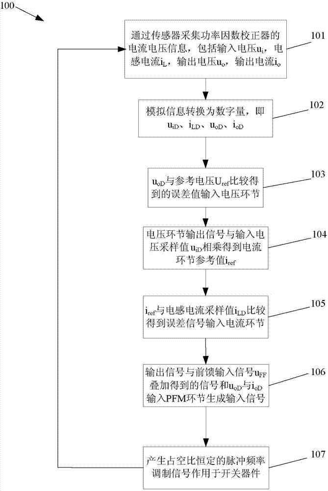
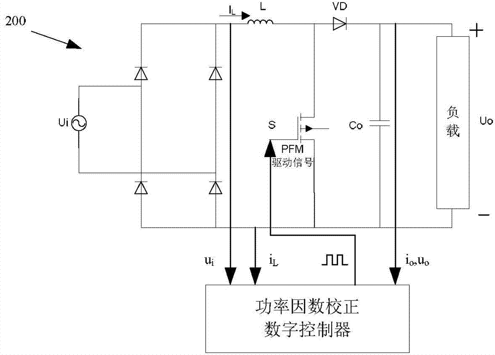
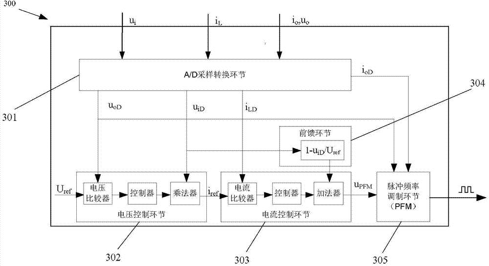
[0023] refer to Figure 1-4 As shown, the flow chart of the digital frequency conversion control method of an embodiment of the present invention specifically includes the following steps:

[0024] First define the following parameter quantities:

[0025] P o - output power, f s - switching frequency, D - duty cycle, L - input boost inductor, u i - input voltage analog, u o - output voltage analog, i L -Inductance current analog quantity, i o - Output current analog, u iD - input voltage digital quantity, u iD(min) -minimum input voltage digital quantity, u oD - output voltage digital quantity, i LD - Inductor current digital quantity, i oD -Output current digital quantity, △u-voltage link deviation signal, △i-current link deviation signal, K p - Adjustable scale factor, T i - Adjustable integral time constant.

[0026] Step...


PUM


Abstract

The invention discloses a digital frequency conversion control method for a power factor corrector. The method comprises the following links: (1) an A / D sampling conversion link: A / D conversion is carried out on ui, iL, uo and io of the power factor corrector through current and voltage sensors to convert the analog values into digital values uiD, iLD, uoD and ioD, which are used as input values of other links; a voltage control link: digital control is carried out on an error value obtained from comparison between the digital value uoD of output voltage and a preset reference voltage value Uref to keep the output voltage stable; a current control link: digital control is carried out on an error value obtained from comparison between the reference current iref provided by the voltage control link and the digital value iLD of inductive current to carry out power factor correction to enable the inductive current to track the input voltage phase; a feedforward link; and a pulse frequency modulation link. The invention aims to provide a digital frequency conversion control method which is capable of reducing the number of peripheral circuits of a controller to the greatest extent under the condition of load change and designed for a power factor corrector.

Description

technical field [0001] The invention relates to the field of switching power supplies, in particular to a digital frequency conversion control method for a power factor corrector. Background technique [0002] The research on power factor correction technology is mainly divided into two aspects: topological structure and control strategy. The topology is the main circuit structure that realizes the function of power factor correction (PFC, Power Factor Correction). It is divided into two types: single-phase and three-phase according to the different forms of the connected grid. According to different applications, different PFC topologies can be designed and used, and no matter what kind of PFC structure is adopted, appropriate control and implementation methods are required. From the current research status, there are mainly two implementation methods: analog and digital . [0003] The analog control system adopted by the traditional power factor correction circuit has be...

Claims


Application Information

Patent Timeline
Patent Type & Authority Applications(China)
IPC IPC(8): H02M1/42
CPCY02B70/10
Inventor 黄智宇徐正龙蒲小华王蓉陈波杨焘
Owner CHONGQING UNIV OF POSTS & TELECOMM
Why Eureka
Try Eureka