Condenser for space solar energy power station

A technology of space solar energy and concentrating mirrors, applied in the field of solar power generation, can solve the problems of high cost of components and launch costs, and achieve the effect of light weight

Inactive Publication Date: 2014-05-07
INST OF PHYSICS - CHINESE ACAD OF SCI
View PDF4 Cites 4 Cited by
  • Summary
  • Abstract
  • Description
  • Claims
  • Application Information

AI Technical Summary

Problems solved by technology

In this way, the larger the capacity of the power station, the more photovoltaic components will be used, so the cost of components and the cost of launch will inevitably be large

Method used


Image

  • Condenser for space solar energy power station

Examples


Embodiment 1

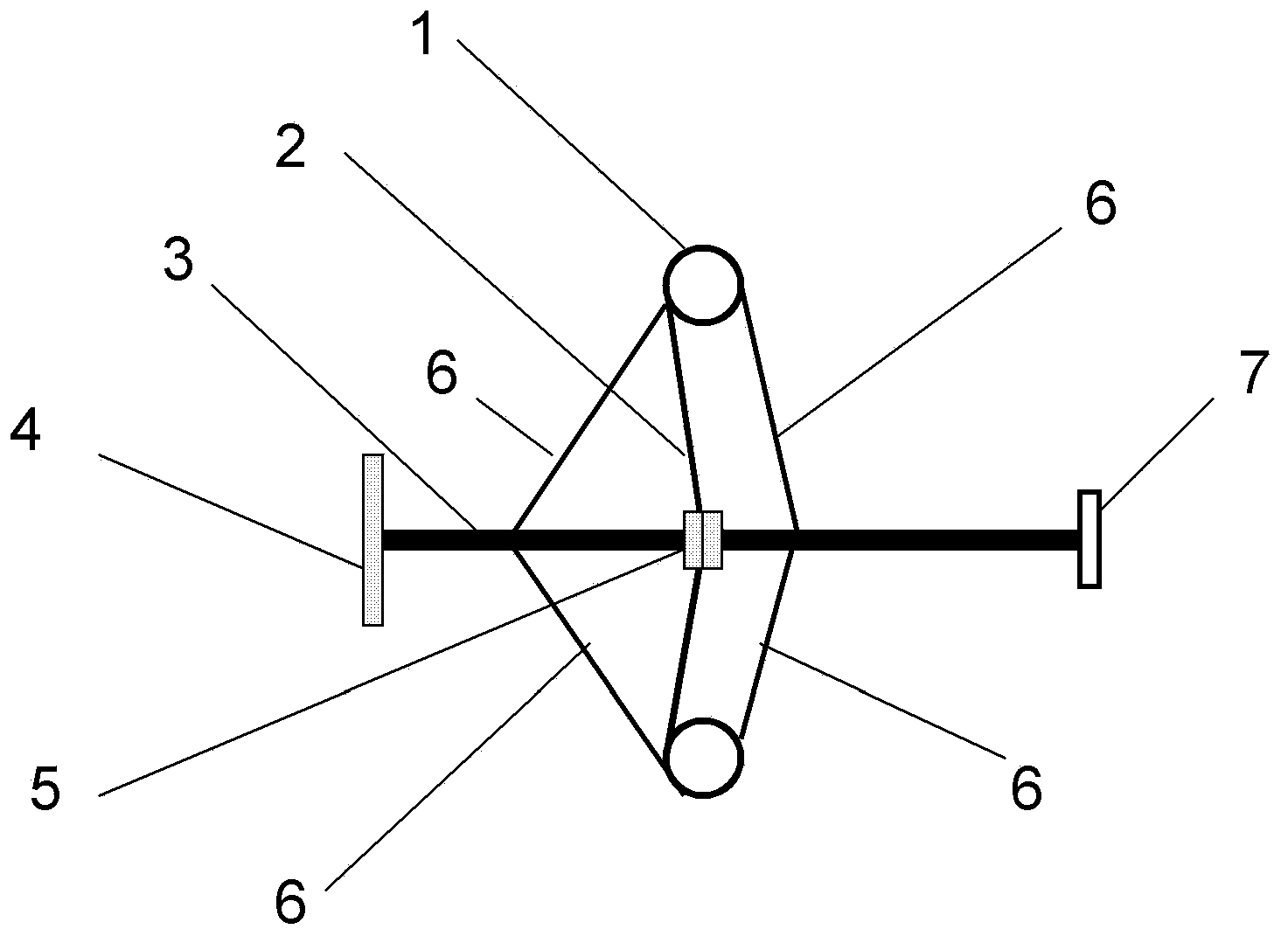
[0041] Such as figure 1 shown. Wherein the annular air bag 1 is made of rubber material with good flexibility and good air tightness. The inner diameter of the annular inflatable bag is 4 centimeters, and the diameter of the expanded circular surface is 2 meters.

[0042] The reflective film 2 is made of flexible plastic film material with good mechanical strength, and the reflective film 2 is pasted on the circular surface of the annular air bag 1 .

[0043]The support bar 3 is made of a lightweight rigid material magnesium-aluminum alloy tube with an outer diameter of 5 centimeters, and the thickness of the tube wall is 5 millimeters.

[0044] The nylon traction rope 6 is connected with the annular inflatable bag 1, and the length of the nylon traction rope 6 is adjusted so that the reflective film 2 forms a conical reflective surface, and the conical reflective surface on the reflective film 2 is coated with a high-efficiency silver reflective coating by coating method. ...

Embodiment 2

[0049] Such as figure 1 shown. The annular air bag 1 is made of nylon material with good flexibility and good airtightness. The inner diameter of the annular inflatable bag is 6 centimeters, and the diameter of the circular surface after expansion is 8 meters.

[0050] The reflective film 2 is made of flexible and mechanically strong plastic film material, on which a high-efficiency aluminum reflective layer is coated with a coating method, and the reflective film 2 is pasted on the circular surface of the annular air bag 1.

[0051] The support rod 3 is made of a light-weight rigid material magnesium-aluminum alloy tube with an outer diameter of 5 cm, and the thickness of the tube wall is 5 mm. The central part of the support rod 3 and the reflective film 2 is passed through bolts and two small aluminum splints 5 with a diameter of 8 cm. fixed together. Connect with the annular inflatable bag 1 by nylon traction rope 6. One end of the support rod 3 is fixed together with ...

Embodiment 3

[0055] Such as figure 1 shown. The annular inflatable bag 1 is made of carbon fiber fabric material with good flexibility and good airtightness. The inner diameter of the annular inflatable bag is 8 centimeters, and the diameter of the expanded circular surface is 16 meters.

[0056] The reflective film 2 is made of flexible and mechanically strong plastic film material, coated with a high-efficiency gold reflective coating by a coating method, and pasted on the circular surface of the annular air bag 1.

[0057] The support rod 3 is made of a light rigid material stainless steel tube with an outer diameter of 5 cm, and the thickness of the tube wall is 5 mm. The central part of the support rod 3 and the reflective film 2 is fixed together by bolts and two small aluminum splints 5 with a diameter of 8 cm. , connected with the annular air bag 1 through the carbon fiber traction rope 6 . One end of the support rod 3 is fixed together with the bracket through a stainless steel ...


PUM


Abstract

This invention discloses a condenser for a space solar energy power station which comprises an annular inflatable air bag made of flexible materials. A light-reflecting thin film made of flexible materials is fixed on the annular surface of the annular inflatable air bag; a support rod made of rigid materials passes through the center of the light-reflecting thin film and is fixed with the light-reflecting thin film; the focus where the support rod is positioned on the light-reflecting thin film surface is provided with a photovoltaic member; the annular inflatable air bag is connected to the support rod through pulling ropes; the lengths of the pulling ropes can be adjusted to enable the light-reflecting thin film to form a cone-shaped reflection surface and the apex angle of the cone-shaped reflection surface can be adjusted; the cone-shaped reflection surface is plated with a light-reflecting layer; and when the annular air bag is in an inflating state, the light-reflecting thin film which is in a foldable state is expanded. The condenser for the space solar energy power station is characterized in that the ratio of the expanding area to the folding volume is high, which is beneficial for rocket emission, and an oversized condensation solar reflector is obtained. The condenser for the space solar energy power station is applicable to the space solar energy power station and the earth solar energy power station.

Description

technical field [0001] The invention belongs to the field of solar power generation, and relates to a foldable super-large concentrating mirror prepared by using an air pressure memory element, and more particularly to a concentrating mirror for space solar power stations. Background technique [0002] The idea of ​​building solar power plants in space has been proposed as early as 1968, but it is only recently that humans have started to really put it into action. Japan is one of the pioneers of this project, which is expected to cost US$21 billion and generate one gigawatt of electricity for 294,000 households. [0003] The intensity of sunlight in space is 5-10 times greater than that on the ground. Solar power technology can provide constant and non-polluting energy, which is very different from the intermittent and cloud-covered solar energy on the ground, and it does not emit pollutants like fuel power plants, nor does it emit pollutants like nuclear power plants Gen...

Claims


Application Information

Patent Timeline
Patent Type & Authority Applications(China)
IPC IPC(8): H02S40/22G02B19/00
CPCY02E10/52
Inventor 周岳亮石洪菲王灿何萌吕惠宾杨国桢
Owner INST OF PHYSICS - CHINESE ACAD OF SCI
Why Eureka
Try Eureka