Eureka AIR delivers breakthrough ideas for toughest innovation challenges, trusted by R&D personnel around the world.

Process for treating landfill leachate

A technology for landfill leachate and treatment process, which is applied in the field of biofilm denitrification and decarbonization combined treatment of landfill leachate, which can solve the problem of increasing land area and investment funds, sludge cultivation being susceptible to external interference, and complex operation and management. and other problems, to achieve the effect of shortening the residence time, easy maintenance and repair, and improving the efficiency of denitrification treatment.

Inactive Publication Date: 2015-04-01
UNIV OF SHANGHAI FOR SCI & TECH
View PDF4 Cites 0 Cited by
  • Summary
  • Abstract
  • Description
  • Claims
  • Application Information

AI Technical Summary

Problems solved by technology

Among them, the activated sludge method is widely used and the operation is relatively stable, but the process is long, the floor area is large, the operation and management are complicated, the sludge cultivation is easily disturbed by the outside world, and the operation cost is high, especially in the treatment of waste with high ammonia nitrogen content. When the leachate is used, the treatment effect is significantly inhibited and the effluent is unstable
However, the ordinary biofilm method needs to set up a secondary sedimentation tank, which increases the floor area and investment funds.

Method used


Image

  • Process for treating landfill leachate
  • Process for treating landfill leachate

Examples


Embodiment 1

[0031] In this embodiment one, the leachate of a certain waste-to-energy plant is selected for treatment. The garbage leachate treatment station of the waste-to-energy plant is used as supporting facilities to treat the garbage leachate in the garbage storage pit, with a processing capacity of 150m 3 / d.

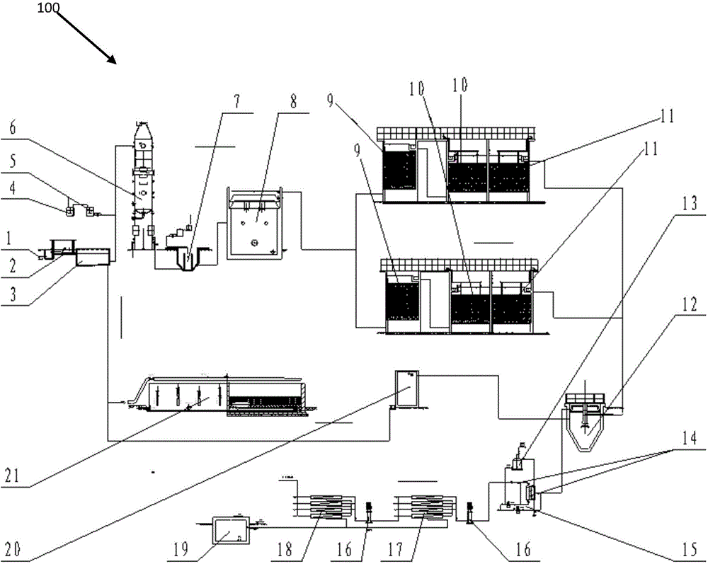
[0032] figure 1 It is a structural schematic diagram of the landfill leachate treatment system involved in the present invention in Embodiment 1.

[0033] Such as figure 1 As shown, the landfill leachate treatment station 100 is provided with:

[0034] Pretreatment device: including garbage leachate tank 1, grid 2 and regulating sedimentation tank 3 connected in sequence, garbage leachate tank 1 is used to store garbage leachate, grid 2 is used to remove large suspended matter, Adjust the specification of the sedimentation tank 3 to 12m×8m×4m, which is used to remove small suspended solids;

[0035] The ammonia removal device includes the alkali storage tank 4, the alka...

Embodiment 2

[0069] In this embodiment two, the garbage fermentation liquid of a certain garbage incineration power plant is selected for processing, and the processing capacity is 200m 3 / d. Influent COD of the garbage fermentation broth Cr The concentration is 50000mg / L, NH 3 - The concentration of N is 3000mg / L, the concentration of SS is 4000mg / L, and the pH is between 6.0 and 9.0. The water quality of the garbage fermentation liquid is unstable.

[0070] In Example 2, the waste fermentation broth is pretreated by using grilles and coagulation sedimentation tanks. Coagulation sedimentation not only effectively reduces the content of suspended solids in the fermentation broth, but also reduces COD. In the obtained pretreatment solution, COD Cr The removal rate was 75%.

[0071] After deammonization treatment in the ammonia distillation tower, the removal rate of ammonia nitrogen in the obtained primary treatment liquid reaches 95%.

[0072] Biodegradation is treated with anaerobic...


PUM

PropertyMeasurementUnit
particle diameteraaaaaaaaaa

Abstract

The invention provides a process for treating a landfill leachate. The process is characterized by comprising the steps of 1, pretreating the landfill leachate to obtain a pretreated liquid, 2, feeding the pretreated liquid into a deamination device for deamination treatment to obtain a primary treated liquid, 3, introducing the primary treated liquid into an anaerobic biotreatment device for biodegradation to obtain a secondary treated liquid, and 4, introducing the secondary treated liquid into at least one group of biological aerated filters for denitrification and decarburization treatment to obtain a third-stage treated liquid which is up to the emission standard. According to the process for treating the landfill leachate, as the deamination treatment, the biodegradation and the denitrification and decarburization treatment are orderly performed on the landfill leachate, the obtained third-stage treated liquid is up to the national sewage emission standard, and therefore, the treatment process is short in flow and simple in method.

Description

technical field [0001] The invention belongs to the field of sewage treatment, and in particular relates to a process for combined treatment of landfill leachate by adopting deamination, biodegradation, and biofilm denitrification and decarburization. Background technique [0002] With the acceleration of urbanization and the rapid development of the global economy, the amount of urban waste has also increased exponentially. Waste incineration and sanitary landfill are important means of urban waste disposal. Among them, waste incineration power generation can not only efficiently realize the reduction and harmlessness of waste, but also turn waste into treasure and realize reuse, so it is more and more widely used. Using waste incineration to generate electricity requires storing a large amount of waste for use, but the stored waste will contain a certain amount of sewage, and during the storage process, the organic matter in the waste will decompose to produce a certain am...

Claims


Application Information

Patent Timeline
Patent Type & Authority Patents(China)
IPC IPC(8): C02F9/14
Inventor 周海东刘建波王蒙周姣岩王学连张倩倩
Owner UNIV OF SHANGHAI FOR SCI & TECH
Why Eureka
Eureka Blog
Learn More