
Cubic boron nitride ultrahigh pressure sintered body cutting tool and surface coated cutting tool

A cubic crystal boron nitride, boron nitride-based technology, applied in the field of cutting tools, can solve the problem of reduced cBN particle-binding phase interface adhesion, reduced toughness of cBN sintered body, and inability to control the size and formation of Ti boride phase. Form and other issues

Active Publication Date: 2014-05-14
MITSUBISHI MATERIALS CORP
View PDF7 Cites 8 Cited by
  • Summary
  • Abstract
  • Description
  • Claims
  • Application Information

AI Technical Summary

Problems solved by technology

[0009] The cBN sintered bodies shown in the above-mentioned Patent Documents 1 and 2 are all obtained by making high-hardness Ti boride (TiB 2 ) phase is dispersed in the binder phase to improve the wear resistance of the cBN sintered body. In the case where band-like or film-like Ti boride phases are formed at the interface between cBN particles and the binding phase, or bulk Ti boride phases are formed in the binding phase
[0010] In addition, in this case, the decrease of the adhesive force at the interface between the cBN particles and the binder phase and the difference in the thermal expansion coefficient become the starting point, which easily leads to the occurrence / progression of cracks, and the toughness of the cBN sintered body decreases. s reason
[0011] In particular, when a cBN sintered body is used as a cutting tool, since a high load, impact, etc. act on the cBN sintered body during cutting, chipping and breakage due to a decrease in toughness become a serious problem
[0012] In addition, the cBN sintered body shown in Patent Document 3 contains W in the sintered body, so Ti boride phase and W boride phase are simultaneously formed during sintering, but the generation of W boride phase suppresses the cBN particle-bonding phase interface. Therefore, the cBN particle-bonded phase interface adhesion force is reduced, which becomes the starting point of crack generation, and there is a problem that the fracture resistance is reduced

Method used


Image

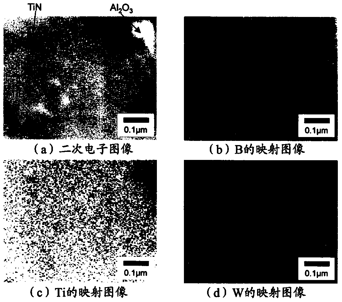
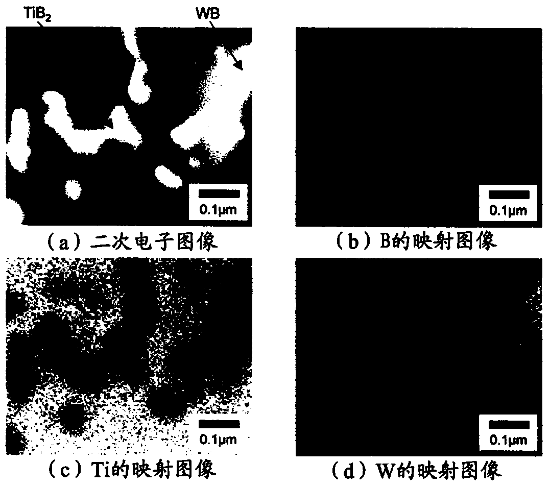
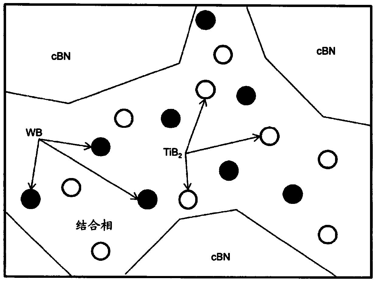
  • Cubic boron nitride ultrahigh pressure sintered body cutting tool and surface coated cutting tool
  • Cubic boron nitride ultrahigh pressure sintered body cutting tool and surface coated cutting tool
  • Cubic boron nitride ultrahigh pressure sintered body cutting tool and surface coated cutting tool

Examples


Embodiment

[0066] (a) First, as shown in Table 1, raw material powder composed of predetermined components and compounding ratios constituting the binder phase of the sintered compact was prepared.

[0067] (b) Next, the above-mentioned raw material powder was filled together with cemented carbide balls and acetone into a cemented carbide-lined ball mill, and the lid was closed, followed by pulverization and mixing by a rotary ball mill.

[0068] (c) Next, hBN powder and WC powder with an average particle size shown in Table 2 were added in such a manner that the addition ratios shown in Table 2 were the same with respect to the total weight of the powder, and the same in the ball mill were carried out in Table 2. Crush and mix for the indicated time.

[0069] (d) Next, to the pulverized and mixed hBN powder and the raw material powder for forming a binder phase, the average particle diameter shown in Table 2 was added so that the addition ratio shown in Table 2 was the same with respect...


PUM

PropertyMeasurementUnit
particle sizeaaaaaaaaaa

Abstract

The invention provides a cutting tool and a surface coated cutting tool. The cutting tool is excellent in defect resistance, and a cBN ultrahigh pressure sintered body with excellent toughness is adopted to be a tool base body. The cBN ultrahigh pressure sintered body containing cBN particles, a combination phase, TiB2 phases and WB phases are employed to be tool base bodies of the cutting tool and the surface coated cutting tool. In terms of the cubic boron nitride ultrahigh pressure sintered body, the average particle size of the cBN particles is 0.5 to 3.5 micrometers, and the content is 40 to 75%; the slightly thin TiB2 phases and the WB phases, 50 to 500 nanometers in average particle size, are dispersedly distributed in the combination phase; 15% to 35% contents of the combination phase are at least more than one of nitrides and oxides of Al, the remaining being at least more than one of nitrides, carbides, borides or carbontrides of Ti and being inevitable impurities; and a relationship, 0.5<=(the production of the WB phases) / (the production of the TiB2 phases)<=1.0, is satisfied.

Description

technical field [0001] The present invention relates to a cutting tool (hereinafter referred to as cBN tool) composed of a cubic boron nitride (hereinafter referred to as "cBN")-based ultra-high pressure sintered body (hereinafter referred to as cBN sintered body) with excellent toughness. Background technique [0002] It is known from the past that cBN sintered body has excellent durability, thermal stability and thermal conductivity, and is also excellent in impact resistance and friction coefficient, and has low affinity with iron-based materials, so it is used to make use of these characteristics. It is used as cutting tool material for steel, cast iron and other iron workpieces. [0003] For example, as shown in Patent Document 1, there is proposed a method of obtaining a cBN sintered body by pulverizing and mixing raw material powder containing a Ti-based compound using a ball mill, blending and mixing it with cBN powder to produce a molded body, and subjecting it to ...

Claims


Application Information

Patent Timeline
Patent Type & Authority Applications(China)
IPC IPC(8): C04B35/5831C04B35/622
Inventor 油本宪志宫下庸介
Owner MITSUBISHI MATERIALS CORP
Learn More