A method for detection and processing of front lone stone cave for shield tunneling construction

A processing method, the technology of the shield method, which is applied in the directions of measuring devices, earthwork drilling and mining, and radio wave measurement systems, can solve the problems of inability to realize vertical detection outside the hole, difficulty in realizing full-section detection, and difficulty in measurement and positioning, and achieve Good use effect, convenient realization and reasonable design effect

Active Publication Date: 2016-02-24
CHINA RAILWAY FIRST GRP CO LTD +1
View PDF6 Cites 3 Cited by
  • Summary
  • Abstract
  • Description
  • Claims
  • Application Information

AI Technical Summary

Problems solved by technology

In actual construction, the existing boulder detection methods mainly have the following defects and deficiencies: ①The number of detection holes (that is, drilling hole 2) is large, and it is difficult to realize full-section detection within the excavation range; ②If there is a building directly above the shield tunnel (Structure) buildings, it will not be possible to realize vertical detection outside the hole; ③The large detection hole needs to be filled in the later stage to prevent the slurry from emerging during shield tunneling; ④Drilling holes vertically when constructing in large rivers, rivers or seas Construction requires large-scale water surface equipment, which is costly and complicated; ⑤Once a boulder is found, if precise blasting is required, vertical drilling must be carried out from the ground, which is difficult to measure and locate, and will affect the blasting effect

Method used


Image

  • A method for detection and processing of front lone stone cave for shield tunneling construction
  • A method for detection and processing of front lone stone cave for shield tunneling construction
  • A method for detection and processing of front lone stone cave for shield tunneling construction

Examples


Embodiment Construction

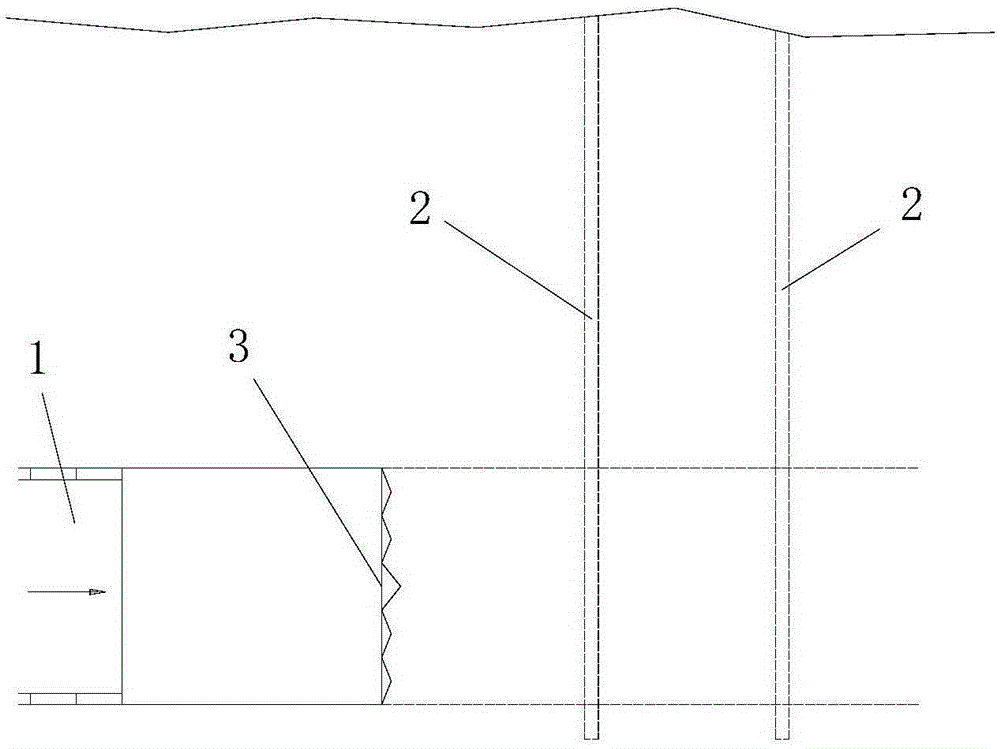
[0044] Such as Figure 4 A method for detecting and processing the lone rock in front of the cave for shield tunneling construction includes the following steps:

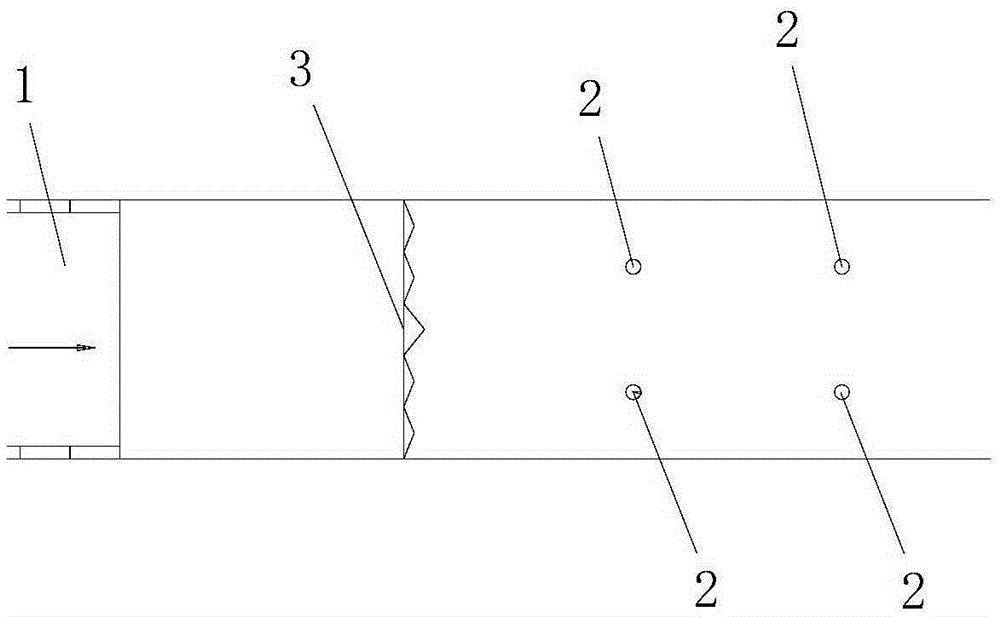
[0045] Step 1. Drilling detection holes in advance: through multiple drilling channels 4 arranged on the cutter head 3 of the shield machine, multiple detection holes 5 are drilled in front of the cutter head 3 of the shield machine from the back to the front. The construction status is detailed. See Figure 5 .

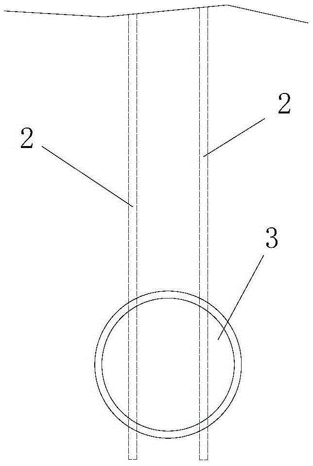
[0046] Such as Image 6 As shown, a plurality of detection holes 5 are arranged along the axial direction of the shield tunnel 1 to be constructed. The shield machine cutterhead 3 is a circular cutterhead, and a plurality of the drilling passages 4 are circular through holes arranged along the central axis of the circular cutterhead, and a plurality of the detection holes 5 are respectively It is arranged coaxially with the plurality of drilling channels 4 . The plurality of drilling channels 4 includ...


PUM

PropertyMeasurementUnit
pore sizeaaaaaaaaaa
lengthaaaaaaaaaa
pore sizeaaaaaaaaaa

Abstract

The invention discloses a method for detecting and processing the front lone stone cave for shield tunneling construction, which comprises the following steps: Step 1, drilling the detection hole in advance: through multiple drilling passages arranged on the cutter head of the shield tunneling machine, the Drill multiple detection holes in front of the cutter head of the shield machine from back to front; step 2, boulder detection: use an ultrasonic detector and use multiple detection holes to detect boulders, the process is as follows: 201. Ultrasonic transmitter and ultrasonic receiver 202. Ultrasonic detection: move the installed ultrasonic transmitter and ultrasonic receiver synchronously from back to front or from front to back, and perform ultrasonic testing on the formation strength at each moving position during the movement process; step 3, Boulder treatment: Blast the boulders in front of the cutter head of the shield machine. The method of the invention has the advantages of simple steps, reasonable design, convenient realization and good use effect, and can solve various defects and deficiencies existing in the boulder detection method adopted in the existing shield tunneling construction.

Description

technical field [0001] The invention belongs to the technical field of shield tunneling, and in particular relates to a detection and processing method for a front boulder cave used in shield tunneling construction. Background technique [0002] The 21st century is an era of great development of tunnels and underground spaces. Shield tunneling construction is being used more and more in the development of underground spaces. However, the geological regions of our country vary greatly, and uniaxial saturation is often encountered in shield tunneling construction. Boulders with extremely high compressive strength seriously endanger the normal excavation construction of shield tunneling. The commonly used boulder detection method is: use drilling or geophysical prospecting methods to detect boulders on the surface, and then carry out targeted deep hole blasting. The detection pertinence of the existing boulder detection methods is not strong, the number of drilling holes is la...

Claims


Application Information

Patent Timeline
Patent Type & Authority Patents(China)
IPC IPC(8): E21D9/08G01S5/20G01N29/07G01B17/00F42D3/00
Inventor 孔凡强杨育僧张剑朱汝威邹超石银生李海生刘仲宁
Owner CHINA RAILWAY FIRST GRP CO LTD
Why Eureka
Try Eureka