
Wavelength converter, manufacturing method thereof and related wavelength conversion device

A technology of wavelength conversion and wavelength conversion layer, which is applied in projection devices, instruments, optics, etc., and can solve problems such as poor reflection coating effect and rough microstructure

Active Publication Date: 2014-05-14
APPOTRONICS CORP LTD
View PDF4 Cites 21 Cited by
  • Summary
  • Abstract
  • Description
  • Claims
  • Application Information

AI Technical Summary

Problems solved by technology

However, the surface of the microstructure processed by this method is rough, and the effect of coating the reflective film on the surface of the microstructure is not good.

Method used

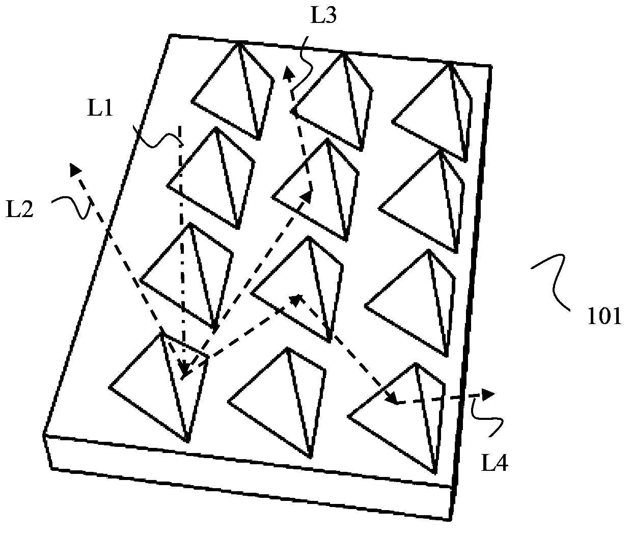
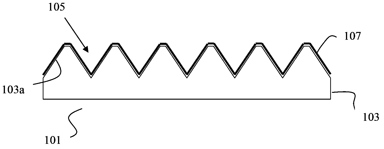
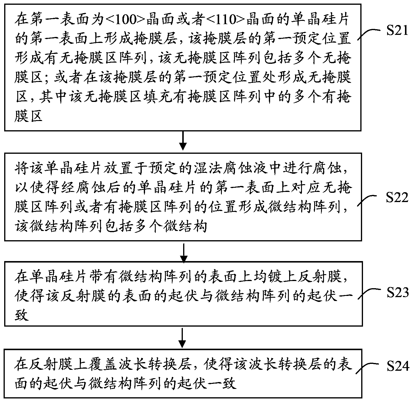

Image

  • Wavelength converter, manufacturing method thereof and related wavelength conversion device
  • Wavelength converter, manufacturing method thereof and related wavelength conversion device
  • Wavelength converter, manufacturing method thereof and related wavelength conversion device

Examples


Embodiment 1

[0035] According to the relationship between the surface orientation of the single crystal silicon wafer and its single crystal lattice orientation, the single crystal silicon wafer is divided into single crystal silicon wafer, single crystal silicon wafer and single crystal silicon wafer, respectively It means that the plane direction of the surface of the silicon wafer is the crystal plane, the crystal plane and the crystal plane of the silicon single crystal. When monocrystalline silicon is etched in alkaline solution, it exhibits anisotropic corrosion characteristics, that is, different crystal planes of silicon are etched at different rates. The etchant has the fastest corrosion rate on the crystal plane, followed by the crystal plane, and finally the crystal plane. hundreds of times faster.

[0036] Therefore, the formation of a microstructure array on the surface of a single-crystal silicon wafer can be achieved through the huge difference in the etching speed...


PUM


Abstract

The embodiment of the invention discloses a wavelength converter, a manufacturing method thereof and a related wavelength conversion device. The manufacturing method of the wavelength converter comprises the steps of forming a mask layer with a mask-free region on a first surface of a monocrystalline silicon wafer of which the first surface is a <100> crystal face or a <110> crystal face, putting the monocrystalline silicon wafer in predetermined etching solution for etching to form a micro structure array on the first surface, and sequentially forming a reflective layer and a wavelength conversion layer on the surface of the micro structure array. The invention can provide a manufacturing method for a wavelength converter has a smooth-surface micro structure array.

Description

technical field [0001] The invention relates to the technical field of light sources for illumination and display, in particular to a wavelength conversion device, a manufacturing method thereof and a related wavelength conversion device. Background technique [0002] In the lighting system or the light source system of the projection system in the prior art, the excitation light is often used to excite the wavelength conversion material to generate the stimulated light. Because the excitation light power is often too high, the temperature of the wavelength conversion layer rises, which reduces the light conversion efficiency of the wavelength conversion material and shortens the service life of the wavelength conversion device. [0003] To solve this problem, a method commonly used in the prior art is to form a raised microstructure array composed of a plurality of raised microstructures on the surface of the wavelength conversion material layer, and the raised microstructu...

Claims


Application Information

Patent Timeline
IPC IPC(8): G03B21/20G03B21/14
Inventor 杨毅
Owner APPOTRONICS CORP LTD
Learn More