Optical system for stereoprojection and method for carrying out stereoprojection

An optical system and stereo projection technology, applied in stereo photography, optics, optical components, etc., can solve the problems of easily damaged polarizers and liquid crystal cells, decreased 3D stereo display effect, and increased crosstalk between left and right eyes, and achieve 3D stereo The display effect is better, the 3D stereoscopic display effect is good, and the stereoscopic effect is stable and maintained.

Inactive Publication Date: 2014-05-14
SHENZHEN FUTURE 3D EDU TECH CO LTD
View PDF5 Cites 3 Cited by
  • Summary
  • Abstract
  • Description
  • Claims
  • Application Information

AI Technical Summary

Problems solved by technology

[0003] Since the projector continues to play the picture, that is, more than 55% of the emitted light energy will continue to be absorbed by the polarizer, which will cause the polarizer to heat up, its polarization degree and other performance will be reduced, and even damage
Moreover, the general polarizer will be attached to the surface of the liquid crystal variable phase retarder, which will cause the liquid crystal molecules in the liquid crystal cell to absorb most of the heat, and the liquid crystal molecules are very sensitive to temperature, which will affect their birefringence coefficient , causing the optical path difference of its polarization o and e light to change or even fail, which in turn affects the stereoscopic picture effect displayed on the screen
[0004] Due to the energy loss of more than 55%, in order to increase the display brightness, the theater will use a higher power xenon lamp, which greatly increases the cost, and the higher power of the xenon lamp will cause more energy to be absorbed by the polarizer, making the polarizer and liquid crystal Boxes are more prone to damage
The sharp decrease in the parameters such as the degree of polarization of the polarizer will intensify the crosstalk between the left and right eyes, and the 3D stereoscopic display effect will be greatly reduced, which will fall into a vicious circle.

Method used


Image

  • Optical system for stereoprojection and method for carrying out stereoprojection
  • Optical system for stereoprojection and method for carrying out stereoprojection
  • Optical system for stereoprojection and method for carrying out stereoprojection

Examples


Embodiment Construction

[0026] In order to make the object, technical solution and advantages of the present invention clearer, the present invention will be further described in detail below in conjunction with the accompanying drawings and embodiments. It should be understood that the specific embodiments described here are only used to explain the present invention, not to limit the present invention.

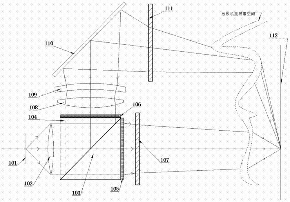
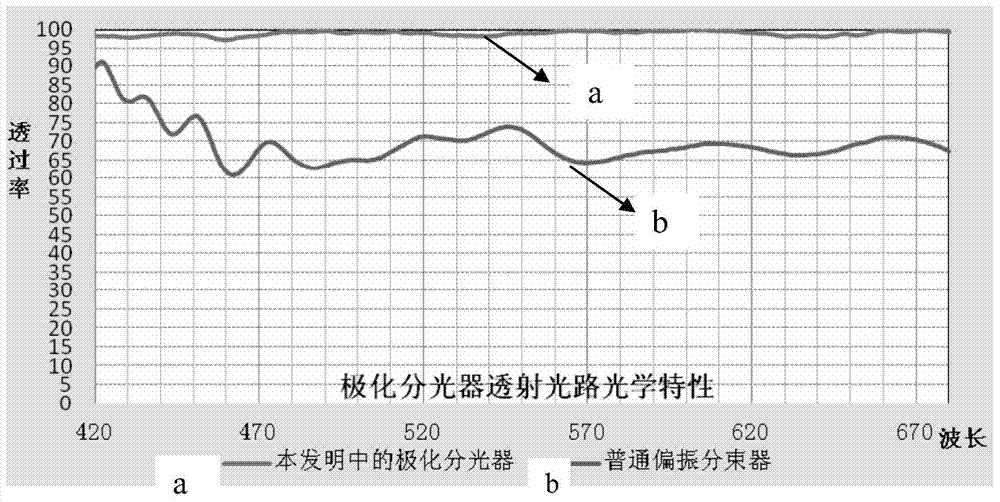
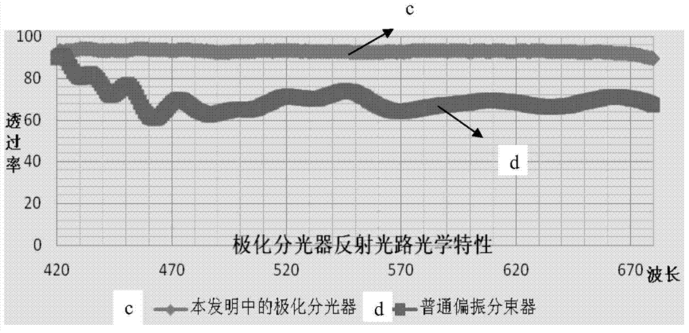
[0027] The optical system of polarization beam splitting, beam combining and zooming of the present invention first converts the natural light (random polarization state) emitted from the object image on the focal plane of the projection objective lens (random polarization state) into P light or S light at the same time after passing through the polarization beam splitter , that is, the transmitted light path and the reflected light path have the same polarization state, the liquid crystal variable phase retarder (LCVR) in the transmitted light path and the reflected light path will synchronize the ...


PUM


Abstract

The invention relates to an optical system for stereoprojection. The optical system for the stereoprojection comprises an object image and a projection objective. The optical system is provided with a transmission light path and a reflection light path. The optical system comprises a polarization beam splitter and a first liquid crystal variable phase retarder in the transmission light path, and the optical system comprises the polarization beam splitter, a first lens or a first lens set, a second lens or a second lens set, a plane mirror having an image rotating function and a second liquid crystal variable phase retarder in the reflection light path, wherein the polarization beam splitter comprises a first triangular prism, a second triangular prism, first plate glass and second plate glass. The invention further provides a method for carrying out the stereoprojection. The optical system can transform more than 97% of the energy of natural light into linearly polarized light, and screen brightness and stereo display fidelity are improved greatly.

Description

technical field [0001] The invention relates to the field of 3D stereoscopic projection display, and more specifically relates to an optical system for stereoscopic projection and a method for stereoscopic projection. The optical system can polarize more than 97% of the energy of natural light into linearly polarized light, greatly improving the image Brightness and stereoscopic display fidelity. Background technique [0002] With the premiere of the Avatar 3D stereoscopic movie in 2009, the 3D craze sounded all over the world. At present, most theaters support 3D playback, and the display chip is Texas Instruments DMD (Digital Micro mirror Device, digital micromirror device) DLP (Digital Light Processing, Digital Light Processing) projectors are used in most theaters. Since the light source used is a xenon lamp, the light emitted is natural light, that is, the polarization state is randomly generated, and to realize stereoscopic display, it needs to be polarized into linea...

Claims


Application Information

Patent Timeline
Patent Type & Authority Applications(China)
IPC IPC(8): G03B35/26G02B27/26G02B30/25
CPCG03B35/26G03B35/22G02B30/25
Inventor 刘飞龚杰苏鹏华
Owner SHENZHEN FUTURE 3D EDU TECH CO LTD
Why Eureka
Try Eureka