Method and device for measuring light frequency through high-power optical fiber optics frequency comb

An optical frequency comb and fiber optics technology, applied in the field of laser science and technology, can solve the problems of no measurement of absolute laser frequency, limited system stability, high requirements for optical comb devices, etc., and achieve fast measurement methods, high degree of integration, small size effect

Active Publication Date: 2014-05-14
CHONGQING HUAPU INFORMATION TECH CO LTD
View PDF3 Cites 20 Cited by
  • Summary
  • Abstract
  • Description
  • Claims
  • Application Information

AI Technical Summary

Problems solved by technology

However, the existing optical comb beat frequency method requires the optical comb seed source to work at a high repetition rate of hundreds of MHz or even GHz. The high repetition frequency optical comb has high requirements on the device, the system stability is limited, and the measurement accuracy is limited; secondly, The existing optical comb beat frequency method does not measure the absolute frequency of the laser, and two optical combs are required to directly read out the optical frequency, or the use of measuring instruments such as a wavelength meter for calculation, which undoubtedly adds inconvenience to the entire measurement process

Method used


Image

  • Method and device for measuring light frequency through high-power optical fiber optics frequency comb
  • Method and device for measuring light frequency through high-power optical fiber optics frequency comb
  • Method and device for measuring light frequency through high-power optical fiber optics frequency comb

Examples


Embodiment 1

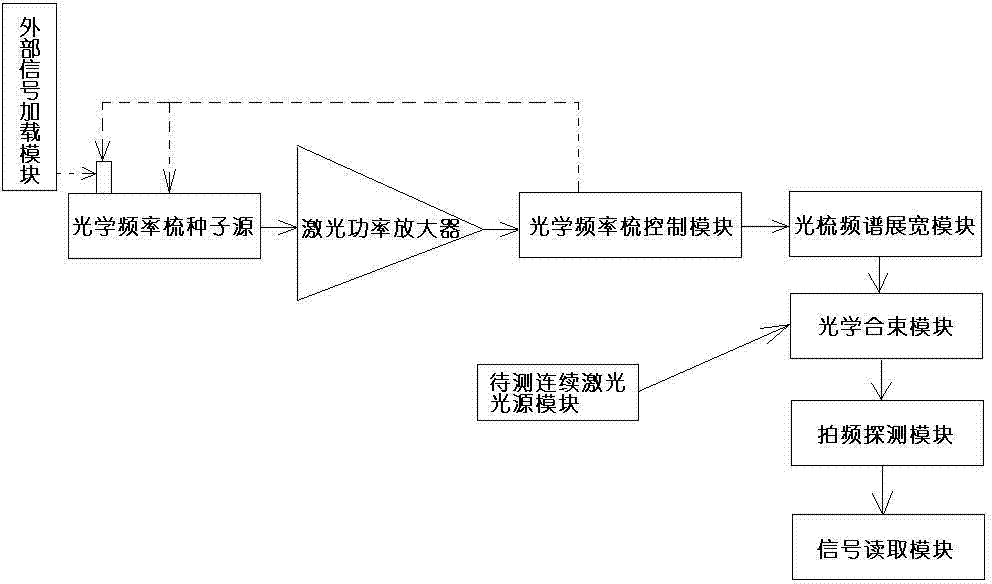
[0032] Embodiment one: if figure 1 As shown, this embodiment specifically relates to a method and device for measuring optical frequency with a high-power fiber optic frequency comb, that is, measuring figure 1 The laser frequency output by the continuous laser light source module to be tested is shown in . The device includes an optical frequency comb, an optical comb spectrum broadening module, an optical beam combining module, a beat frequency detection module and a signal reading module arranged in sequence from the beginning to the end. The optical frequency comb is composed of an optical frequency comb seed source, a laser power amplification module, and an optical frequency comb control module. There is a feedback connection relationship between the optical frequency comb control module and the optical frequency comb seed source; the optical frequency comb seed source An external signal loading module is also arranged on the top, and a continuous laser light source mo...

Embodiment 2

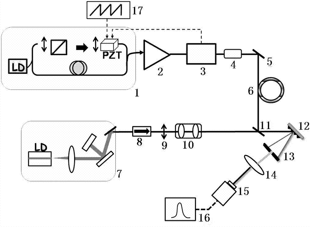
[0048] Embodiment two: if figure 2 Shown is a schematic diagram of using a polarization rotation-locked mode fiber laser as the optical frequency comb seed source, and the output light of the 657nm external cavity semiconductor laser as the laser to be measured, and measuring its optical frequency with a high-power optical frequency comb.

[0049] (1) The optical frequency comb seed source 1 adopts a half-space and half-fiber structure, using a 980nm semiconductor laser LD as a pump source, a single-mode ytterbium-doped fiber as a gain medium, and an intracavity space isolator to ensure the unidirectional operation of the laser. The ceramic crystal PZT is installed on the high reflection mirror in the cavity; the spatial wave plate in the cavity is adjusted to make the laser reach a stable mode-locked state;

[0050] (2) The laser power amplifier 2 adopts a two-stage amplification structure. The gain fiber of the pre-amplifier is a single-mode fiber doped with ytterbium, whic...

Embodiment 3

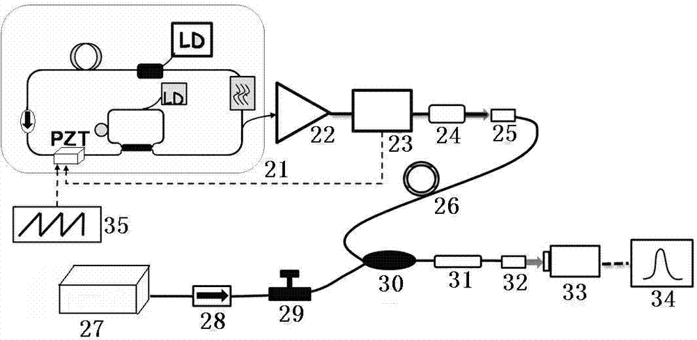
[0060] Embodiment three: as image 3 Shown is a schematic diagram of using a fiber loop mirror structure laser as the optical frequency comb seed source, using the output light of the 1064nm fiber laser as the laser to be measured, and measuring its frequency with an optical frequency comb.

[0061] (1) The optical frequency comb seed source 21 adopts a fiber optic ring mirror structure, uses a 980nm semiconductor laser LD as a pump source, and a single-mode ytterbium-doped fiber as a gain medium; piezoelectric ceramic crystal PZT is wound on the single-mode fiber of the laser cavity ; Adjust the fiber polarization controller to make the semiconductor laser LD reach a stable mode-locked state;

[0062] (2) Since the wavelength band of the laser to be measured is similar to the output light band of the optical frequency comb seed source 21, the optical fiber power amplifier 22 adopts a single-stage amplification structure, and a 1 μm band optical fiber isolator is used in front...


PUM


Abstract

The invention discloses a method and device for measuring the light frequency through a high-power optical fiber optics frequency comb. A mode locking pulse laser serves as an optics frequency comb seed resource to set up the high-power optical fiber optics frequency comb, and a carrier envelope phase signal of the optics frequency comb is locked at the zero frequency; the beat frequency is carried out on the output light of the optics frequency comb and continuous lasers to be tested, the repeated frequencies of the pulse of the optics frequency comb seed resource are finely adjusted through an externally loaded modulation signal, a plurality of sets of beat frequency signals corresponding to different repeated frequencies are obtained, and therefore the accurate measuring of the frequency of the continuous lasers to be tested can be achieved. The method and device have the advantages that the device is stable in structure, the measuring process is easy, and the application is flexible.

Description

technical field [0001] The invention belongs to the field of laser science and technology, in particular to a method and device for measuring optical frequency with a high-power fiber optical frequency comb. Background technique [0002] The development of science and technology needs to be established on the basis of precise experimental measurement. As the measurement reference value, optical frequency determines the accuracy and definition of many other physical quantities. The precise measurement of optical frequency means the improvement of measurement accuracy, which not only provides a more precise time-frequency reference for the determination of many basic physical constants, but also facilitates the development of atomic clocks with microwave quantum frequency standards as the core, which will improve the global The accuracy of the positioning system builds an information highway. Today, with the increasing development of information technology, the research of hi...

Claims


Application Information

Patent Timeline
Patent Type & Authority Applications(China)
IPC IPC(8): H01S3/13H01S3/0941H01S3/098
Inventor 白东碧曾和平
Owner CHONGQING HUAPU INFORMATION TECH CO LTD
Why Eureka
Try Eureka