Building foundation type sandy soil heat storage self-heating system

A heating system and ground-based technology, applied in the field of HVAC, can solve the problems of energy consumption, demand mismatch, poor controllability of heat release process, etc., to reduce construction and installation costs, reduce insulation and moisture-proof costs, and reduce repeated construction costs Effect

Inactive Publication Date: 2014-05-21
LANZHOU UNIVERSITY OF TECHNOLOGY
View PDF9 Cites 3 Cited by
  • Summary
  • Abstract
  • Description
  • Claims
  • Application Information

AI Technical Summary

Problems solved by technology

[0004]1. Heat storage materials are not easy to obtain
Pebbles are used as heat storage materials. Although pebbles are cheap, for areas such as plains, deserts, and high loess sources, pebbles are not easy to obtain, and they have to be transported over long distances, so the cost is high; while using concrete as heat storage materials requires large In the case of capacity heat storage, the heat storage needs a large volume, and its cost is high
[0005]2. The heat storage and release performance of deep heat storage body is poor
The above technology heats the room through low-temperature floor radiation. This technology is easier to transfer heat from the surface of the heat storage body to the room through radiation, but for the heat in the deep layer of the heat storage body, it needs to be transmitted to the floor surface first, and then the room heat transfer, so Deep heat is not easy to transfer into the room
[0006]3. Poor controllability of exothermic process
When the sun has just set, the outdoor ambient temperature is high and the required heating power is small, but at this time there is more heat in the heat storage body, and its heat transfer power is larger; and when it is late at night or early in the morning, the outdoor ambient temperature is low and the required heating power is higher. The heating power is large, but at this time the heat in the heat storage body is less, and its heat transfer power becomes smaller. Therefore, the heat transfer power of this method is less controllable and does not match the needs of the room.
[0007]4. Energy consumption during heating
When the low-temperature floor radiant heating method cannot meet the heating power requirements of the room, this technology starts the exhaust fan to directly transport the hot air in the heat storage body to the room. At this time, it needs to consume additional energy to heat the room, which increases the installation cost of the system. and heating operating costs
[0008]5. Requires large temperature differentials to heat effectively
Although the low-temperature floor radiant heating technology has a lower heating temperature than ordinary radiators, it also requires higher heating power when the room temperature is 20°C higher than the room temperature. When the temperature is low, the heating power drops significantly, which cannot effectively guarantee the warm temperature in the room.

Method used


Image

  • Building foundation type sandy soil heat storage self-heating system
  • Building foundation type sandy soil heat storage self-heating system
  • Building foundation type sandy soil heat storage self-heating system

Examples


Embodiment 1

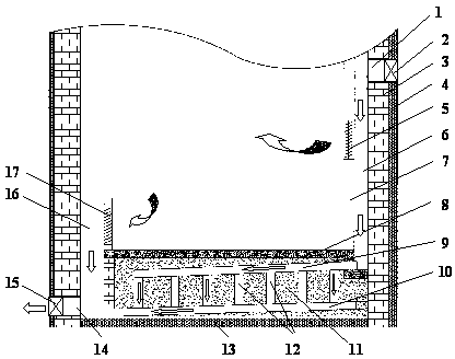
[0020] Such as figure 1 , Figure 11 As shown, a building foundation type sand heat storage self-heating system, which includes a house foundation and a wall 3, and also includes a foundation type sand heat storage self-heating system, which is located on the inner side of two opposite or adjacent wall 3 and is far away from the wall 3 A first partition 7 and a second partition 21 are built at a distance of 1 cm to 50 cm. The space surrounded by the first partition 7 and the enclosure wall 3 constitutes the hot air duct 6 , and the space enclosed by the second partition 21 and the enclosure wall 3 constitutes a The cold air duct 16 is provided with an air inlet 1 on the enclosure wall 3 or the top floor 18 forming the hot air duct 6 , and a first valve or baffle 2 is arranged in each air inlet 1 , forming the cold air duct 16 Open the air outlet 14 on the wall 3 or the top floor 18, in each air outlet 14 is provided with a second valve or baffle plate 15, the first partition...

Embodiment 2

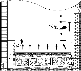
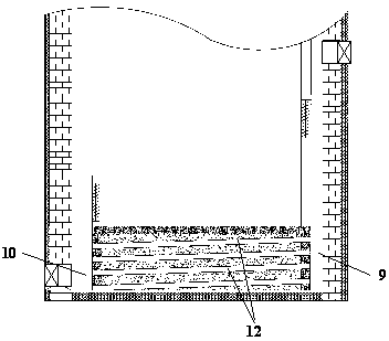
[0034] On the basis of Example 1, the figure 1 , figure 2 The heat exchange tube 12 in the horizontal placement, such as image 3 As shown, the upper diffuser 9 and the lower diffuser 10 are respectively connected to the two ends of the heat exchange tube 12, wherein the upper diffuser 9 communicates with the hot air duct 6, and the lower diffuser 10 communicates with the cold air duct 16 and the outlet. The wind holes 14 communicate with each other. It should be noted that this way of laying the heat exchange tubes horizontally and placing the diffuser vertically has a simple structure, convenient installation, and small air flow resistance, but it is not conducive to heat transfer from the heat storage body in the lower layer to the ground layer. The heat transfer power from the floor to the house is small, so the total heat transfer power of the system is small, and the temperature of the underground heat storage body required is relatively high.

Embodiment 3

[0036] On the basis of Example 1 and Example 2, the figure 2 , image 3 The upper diffuser 9 and the lower diffuser 10 in the Figure 4 Plate diffuser shown. What needs to be explained is that the flow resistance of the plate diffuser is small, and the effect of diverging and converging is good, but the construction process is more complicated, the construction cost is higher, and the overall effect is better.


PUM


Abstract

The invention relates to a building foundation type sandy soil heat storage self-heating system which comprises a building foundation, an enclosing wall and a foundation type sandy soil heat storage self-heating system. The foundation type sandy soil heat storage self-heating system comprises a foundation type sandy soil heat storage device, a hot air duct, a cold air duct, a hot air louver and a cold air louver; the foundation type sandy soil heat storage device comprises a heat storage body, a heat exchange pipe buried in the heat storage body and air diffusers at both ends of the heat exchange pipe. The building foundation type sandy soil heat storage self-heating system has the characteristics of low heat storage cost, large heat storage capacity, high heat exchange efficiency, no energy consumption in the heating process, good performance of regulating and controlling heating power and the like. The system has the advantages of simple structure, safety, reliability, high stability, wide adaptability and the like and is a very ideal sandy soil heat storage self-heating system which is used for a single-layer or multilayer building in the northern area to utilize new energy, such as wind energy, solar energy and the like, to carry out heating.

Description

technical field [0001] The invention relates to the technical field of heating and ventilation, in particular to a heat storage and heating system that utilizes building foundation sand to store heat and can provide self-heating. Background technique [0002] Due to the intermittence and discontinuity of new energy supplied by wind energy and solar energy, and the price of new energy is higher than that of traditional energy, so in the new energy building heating technology, the development of low-cost heat storage heating technology has become the focus. In the low-cost heat storage heating technology, it is very important to select cheap heat storage materials and develop building-integrated self-heating technology. According to the published literature, the heat storage materials for building-integrated design and construction are mainly pebbles and concrete , for residents in some plains, loess plateaus, and desert areas, the cost of obtaining pebbles and concrete materi...

Claims


Application Information

Patent Timeline
Patent Type & Authority Applications(China)
IPC IPC(8): F24D15/00F28D20/00
CPCY02E60/14Y02E70/30
Inventor 王克振
Owner LANZHOU UNIVERSITY OF TECHNOLOGY
Why Eureka
Try Eureka