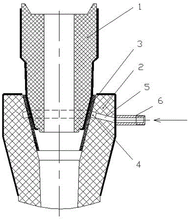
Pouring protecting device and pouring protecting control method for continuously cast ladle

A protection device and continuous casting technology, which is applied in the direction of manufacturing tools, casting equipment, casting melt containers, etc., can solve the problems that people cannot approach the sealing part, the operator cannot find it, and the secondary pollution of molten steel, etc., so as to prevent secondary pollution , Significant economic benefits, the effect of ensuring quality

Active Publication Date: 2014-05-28
石钢京诚装备技术有限公司
View PDF7 Cites 8 Cited by
  • Summary
  • Abstract
  • Description
  • Claims
  • Application Information

AI Technical Summary

Problems solved by technology

In the actual production process, after putting the gasket into the upper mouth of the shroud, the operator uses the manipulator to insert the shroud into the lower nozzle of the ladle. During the process, due to the damage of the gasket, the section of the inner cavity of the shroud is not round, and the matching surface of the bowl mouth Influenced by factors such as dirty steel and slag treatment, it often leads to seal failure, and the open-type quantitative supply of argon gas protection method is effective when the seal part is slightly invalid and the inhaled gas volume is not enough to destroy the argon gas mass. Once the seal part is severely damaged, the argon gas mass cannot When the negative pressure is sufficiently compensated, the protection will fail, causing secondary pollution of molten steel
[0004] During the actual steel pouring process, the sealing part cannot be approached by people and cannot be confirmed. The operator cannot find out if there is a problem with the conventional continuous casting ladle pouring protection device, so it is impossible to take further remedial measures. Therefore, special steel continuous casting production urgently needs to correct the current Ladle pouring protection device and method are improved

Method used


Image

  • Pouring protecting device and pouring protecting control method for continuously cast ladle

Examples


Embodiment Construction

[0020] The protective pouring concept of the present invention is completely different from the existing conventional protective pouring concept.

[0021] The existing conventional protective pouring concept, regardless of whether the seal is effective or not, supplies argon in the external space of the sealed connection in a quantitative manner to form an argon mass protective atmosphere, which is effective when the seal is slightly damaged. Once the seal is damaged, the quantitative argon cannot meet the requirements. When the inhaled air volume is required, the inhaled air is supplemented, and the on-site operator cannot find out, causing substantial secondary pollution of molten steel.

[0022] The protection pouring concept of the present invention is to automatically compensate the argon gas supply to the automatic regulating valve through the PID controller according to the amount of gas volume demand at the sealed connection (set value 0.6Mpa), which belongs to the cons...


PUM


Abstract

The invention discloses a pouring protecting device and a pouring protecting control method for a continuously cast ladle and belongs to the technical field of pouring equipment and methods for continuously cast ladles. The pouring protecting device and the pouring protecting control method are used for improving pouring sealing protecting effect of a molten steel outlet of the ladle. The technical scheme includes that a horizontal annular groove forms on the upper portion of the inner cavity surface of a long molten steel port at the joint of the long molten steel port and the molten steel outlet and is connected with an argon introducing pipe, the argon introducing pipe is connected with an argon supply pipe, and an automatic adjusting valve and a PID (Proportion Integration Differentiation) controller are installed in the argon supply pipeline. According to the sealed portion, for protecting argon demand, the automatic argon adjusting valve is used to automatically compensate argon supply as constant pressure, and an alarm can be provided so as to take emergency measures when sealing failure occurs. The pouring protecting device is convenient to construct and good in sealing effect and is capable of sealing the joint of the molten steel outlet and the long molten steel port so as to prevent the air from entering the molten steel, eliminate secondary pollution of the molten steel and guarantee quality of the molten steel. Meanwhile, argon consumption is reduced, and the pouring protecting device has remarkable economic benefits.

Description

technical field [0001] The present invention relates to a protective pouring protection device and control method for continuous casting ladles, in particular to a non-open type constant pressure supply argon protection device for long nozzles and a pouring protection control method using the protection device, belonging to Continuous casting ladle pouring equipment and method technical field. technical background [0002] During the continuous casting process, when the molten steel flows into the tundish from the ladle through the long nozzle, the flow of molten steel generates negative pressure inside the nozzle, and the air outside the nozzle tends to enter the molten steel through the connection between the nozzle wall and the nozzle. The air entering the molten steel through the nozzle or nozzle connection will have an important impact on the quality of the slab and the blockage of the nozzle. Firstly, the oxygen in the air reacts with the alloying elements in the stee...

Claims


Application Information

Patent Timeline
Patent Type & Authority Applications(China)
IPC IPC(8): B22D11/117B22D11/18B22D41/58
Inventor 董大西李国栋高晗高惠民李荣祥陈良勇范建通郝增林
Owner 石钢京诚装备技术有限公司
Why Eureka
Try Eureka