
Double mechanical sealing method and double mechanical sealing device for kettle gas films
A mechanical seal and double-end face technology, which is applied to engine seals, mechanical equipment, engine components, etc., can solve problems such as increasing costs, and achieve the effects of easy disassembly, accurate installation, and wide applicability
- Summary
- Abstract
- Description
- Claims
- Application Information
AI Technical Summary
Problems solved by technology
Method used
Image


Examples
Embodiment Construction
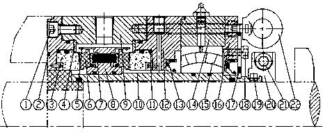
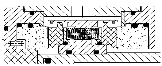
[0010] A gas film double-end mechanical seal method and device for a kettle, comprising a bolt 1, a kettle body O-ring 2, a static ring 3, a static ring pressure plate 4, a moving ring snap ring 5, a moving ring 6, a spring 7, a moving ring Seat 8, shell 9, shaft sleeve 10, static ring O-ring 11, static ring seat 12, oil seal 13, bearing box 14, bearing 15, bearing gland 16, assembly piece 17, screw 18, transmission pin 19, The transmission ring 20, the transmission ring screw 21 and the suspension ring screw 22 are characterized in that: the bolt 1 is installed on the shell 9, the kettle body O-ring 2 is installed on the static ring seat 12, the static ring 3 is supported by double O-rings and Relying on the positioning of the static ring pressure plate 4, the static ring 3 and the moving ring 6 have a hydrodynamic pressure groove on the matching end surface, the moving ring 6 is connected to the moving ring snap ring 5, the spring 7 and the moving ring seat 8 are connected to...
PUM
 Abstract
Description
Claims
Application Information