
Power battery module temperature control system for new energy coach

A temperature control system, power battery technology, applied in batteries, secondary batteries, circuits, etc., can solve the problem that the consistency of heating and heat dissipation of the monomer cannot be well guaranteed, the temperature of the battery module is difficult to control, and the leakage of electricity and water. and other problems, to achieve the effect of improving service life, simple and compact design, and improving utilization rate

Active Publication Date: 2014-05-28
ZHONGTONG BUS HLDG
View PDF4 Cites 14 Cited by
  • Summary
  • Abstract
  • Description
  • Claims
  • Application Information

AI Technical Summary

Problems solved by technology

[0004] At present, domestic mainstream battery manufacturers use resistance wire heating or passive insulation protection in the structural design of vehicle power battery modules; battery cooling adopts a series of cooling measures such as ventilation cooling, liquid cooling, and solid cooling; due to liquid, Solid-state heat dissipation methods all have hidden dangers of electric leakage and water leakage, and the structure is complicated and bulky, which is difficult to use on cars
Therefore, the vehicle power batteries on the market generally adopt ventilation cooling and passive heat preservation protection, but this temperature control method is greatly affected by the external environment temperature. When the external air temperature itself is too low or too high, the temperature of the battery module will be difficult. It is controlled and limited by the structure of the whole vehicle. The internal air duct structure of the battery module cannot well ensure the consistency of heating and heat dissipation of the monomer.

Method used


Image

  • Power battery module temperature control system for new energy coach
  • Power battery module temperature control system for new energy coach

Examples


Embodiment Construction

[0028] The present invention is described in detail below in conjunction with the accompanying drawings:

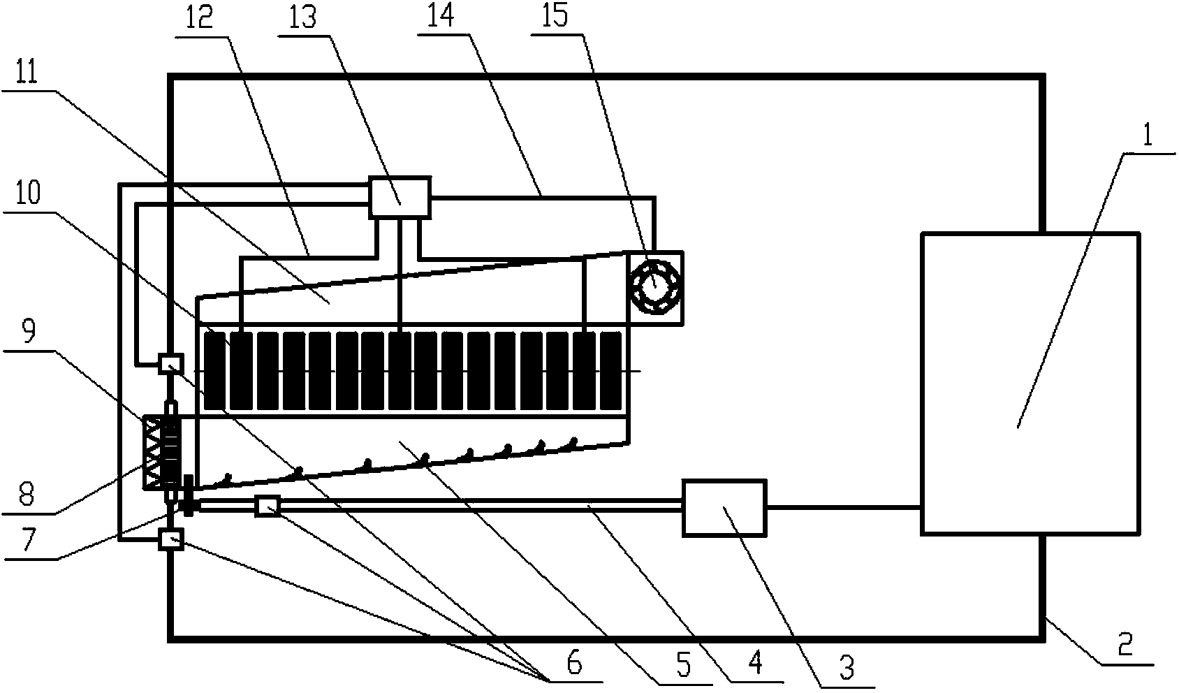
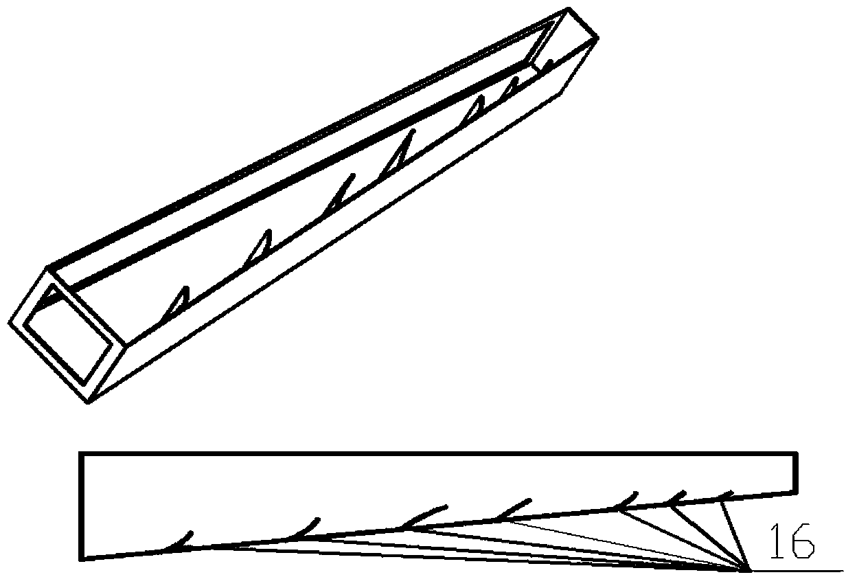
[0029] like Figure 1-2 As shown in the figure, the temperature control system and device for the power battery module for a new energy bus includes the following 4 parts: the battery module 10, the battery management system, the battery heating and cooling device, and the energy supply system;

[0030] The battery management system includes a temperature collection line 12, a CAN communication harness 14, a battery management controller 13, and a solenoid valve 6; the battery heating and cooling device includes a perforated heat sink 8, a vortex tube 7, a battery air inlet shroud 5, and a battery outlet air guide The flow hood 11 , the fan 15 ; the energy supply system includes the engine cooling water pipeline 2 and the air pipeline 4 .

[0031] The cells in the battery module 10 are arranged and fixed in parallel. There is a certain gap between the cells and the cells...


PUM


Abstract

The invention discloses a power battery module temperature control system for a new energy coach, which comprises a battery module, wherein the battery module is connected with a battery management controller through a temperature collecting wire; a battery inlet air guide hood is fixed on one side of the battery module in a sleeving manner; a battery outlet air guide hood is fixed on the other side of the battery module in a sleeving manner; a heating panel and a vortex pipe are fixed at the inlet of the battery inlet air guide hood; a vortex pipe is sequentially connected with a blast pump and a motor through a corresponding electromagnetic valve. According to the power battery module temperature control system for the new energy coach, based on the integral heat management and control of the whole coach, the compressed gas output from the blast pump and motor cooling water heat in the moving coach are mixed as an energy source; the cold gas and hot gas are provided for the battery through the vortex pipe and the heating panel; the temperature control of battery module is realized; the requirement that the battery can work in an optimal temperature range in a cold winter and in a hot summer is satisfied.

Description

technical field [0001] The invention relates to the field of new energy vehicle design and manufacture, in particular to a temperature control system for a power battery module for a new energy passenger vehicle. Background technique [0002] With the continuous deterioration of my country's natural environment, more and more smog weather has seriously affected our living environment. Therefore, the country's requirements and policies for energy conservation and emission reduction are also unprecedentedly increasing. The new energy bus with remarkable effect of energy saving and emission reduction has become the key product promoted by the state, but an important factor restricting the promotion of new energy bus is that the service life of the vehicle power battery is too short. It is a fundamental condition to speed up the promotion of new energy passenger car products. [0003] There are many important factors that affect the service life of automotive power batteries. In ...

Claims


Application Information

Patent Timeline
Patent Type & Authority Applications(China)
IPC IPC(8): H01M10/613H01M10/625H01M10/6563
CPCH01M2220/20Y02E60/10
Inventor 王钦普薛守飞范志先王波刘清波刘涛孙国伟赵佳
Owner ZHONGTONG BUS HLDG
Learn More