Three-level DC converter apparatus and electric energy conversion method employing same

A technology of DC conversion and conversion device, which is applied in the direction of conversion of DC power input to DC power output, output power conversion device, and adjustment of electrical variables, which can solve the complex manufacturing process of high-power transformers and filters, unfavorable installation and maintenance, Unfavorable problems such as converter efficiency, to achieve the effect of increasing the equivalent switching frequency, simple structure, and high reliability

Active Publication Date: 2014-05-28
NO 719 RES INST CHINA SHIPBUILDING IND
View PDF12 Cites 10 Cited by
  • Summary
  • Abstract
  • Description
  • Claims
  • Application Information

AI Technical Summary

Problems solved by technology

The high-voltage MOSFET switch tube has large on-state resistance and large conduction loss, which is not conducive to improving the efficiency of the converter; the high-voltage IGBT switch tube has serious current tailing phenomenon, which limits the increase of switching frequency, which is not conducive to reducing the transformer and filter. Volume, weight and cost; the switching tubes are connected in series, requiring more complex circuits and controls to ensure better synchronous control and voltage equalization between the series switching tubes
In addition, in the above occasions, the input or output current is also very large, and the switch tubes are connected in parallel to meet the high current demand. On the one hand, the device itself is required to have better consistency. This greatly increases the cost of device screening and the difficulty of circuit control, and the reliability of the entire system is also low; moreover, the manufacturing process of high-power transformers and filters is complicated, the cost is high, and it is not conducive to installation And maintenance
[0003] Therefore, at present, there are various problems in the application of traditional converters and technologies in high-voltage and high-power applications, and these problems have not been resolved

Method used


Image

  • Three-level DC converter apparatus and electric energy conversion method employing same
  • Three-level DC converter apparatus and electric energy conversion method employing same
  • Three-level DC converter apparatus and electric energy conversion method employing same

Examples


Embodiment Construction

[0035] The present invention will be further described below in conjunction with the accompanying drawings and specific embodiments.

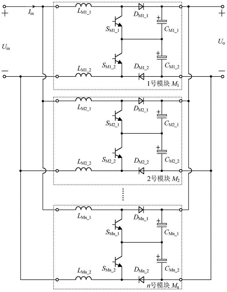
[0036] figure 1 is a main circuit diagram of a three-level DC conversion device according to an embodiment of the present invention. Such as figure 1 As shown, the three-level DC conversion device in this embodiment includes n three-level DC conversion modules M 1 , M 2 ,·····,M i 、·····M n , wherein, i and n are positive integers, i≤n, i represents any one module among 1 to n, and the n three-level DC conversion modules are connected in parallel with each other.

[0037] from figure 1 It can be seen that each three-level DC conversion module includes a first boost inductor L Mi_1 and the second boost inductor L Mi_2 , the first switch tube S Mi_1 and the second switch tube S Mi_2 , the first diode D Mi_1 and the second diode D Mi_2 and the first divider capacitor C Mi_1 and the second divider capacitor C Mi_2 , low voltage DC inp...


PUM


Abstract

The invention discloses a three-level DC converter apparatus and an electric energy conversion method employing the same. The three-level DC converter apparatus comprises n three-level DC conversion modules M1, M2..., Mi,..., and Mn. The n three-level DC conversion modules are connected with each other in parallel. Each module has the same circuit structure and parameters. The electric energy conversion method provided by the invention can perform phase shift control on switch tubes in the modules and among the modules. The three-level DC converter apparatus has the following advantages: the structure is simple, the expansibility is high, the redundancy capability is high, and a low-voltage single switch tube is applied to a high-voltage large-power electric energy conversion occasion; and the control method provided by the method can improve the equivalent switch frequency of the three-level DC converter apparatus to 2n times of an original switch frequency, substantially reduces the pulsation of input current and output voltage, and accordingly greatly reduces the volume, weight and cost of an input and output filter, and at the same time, the efficiency and dynamic performance of a circuit are also enhanced.

Description

technical field [0001] The invention relates to a DC-DC power conversion device, in particular to a three-level DC conversion device suitable for high-voltage and high-power applications and a power conversion method using the device. Background technique [0002] In recent years, the application of power electronics technology in modern industrial society has become more and more extensive, and the requirements for power conversion devices have become higher and higher. major trends in development. In many occasions, such as communication power supplies, three-phase power factor correction converters, ship electrics, high-speed railway electrics, rail transit electrics, etc., their input or output voltages are relatively high, and traditional converters such as Buck, Boost, Buck -Boost, Cuk, SEPIC, Zeta, half-bridge and full-bridge, etc. need to select high-voltage rated switch tubes. The high-voltage MOSFET switch tube has large on-state resistance and large conduction l...

Claims


Application Information

Patent Timeline
Patent Type & Authority Applications(China)
IPC IPC(8): H02M3/155
Inventor 吴浩伟姚川李鹏周樑蔡凯徐正喜陈涛魏华欧阳晖李小谦姜波李可维邢贺鹏金惠峰罗伟耿攀孙朝晖谢炜吴大立余跃听雷津袁阳
Owner NO 719 RES INST CHINA SHIPBUILDING IND
Why Eureka
Try Eureka