
Shaft head extrusion forming system and method

A technology of extrusion molding and control system, applied in metal extrusion, metal extrusion control equipment, metal processing equipment, etc. The effect of short heating time, product quality improvement, and elimination of adverse effects

Active Publication Date: 2014-06-04
GUANGDONG FUWA HEAVY IND
View PDF6 Cites 7 Cited by
  • Summary
  • Abstract
  • Description
  • Claims
  • Application Information

AI Technical Summary

Problems solved by technology

The existing technology used for the axle head is to use solid bar stock, which is reamed and upset on the hydraulic press after local heating in the intermediate frequency heating furnace. The disadvantage of this process is: the solid bar stock 6 (such as Figure 8 As shown) heating before extrusion and rolling takes a long time, which leads to an increase in production costs and uneven heating. At the same time, multiple hot rolling processes are required, which consumes time and energy, and the inner hole of the solid bar 6 is used during the rolling process. The threading process causes thread lines in the inner hole, resulting in unevenness, and more importantly, it is difficult for the rolled solid bar 6 to form full-fiber metal streamlines distributed along the axial direction, resulting in a reduction in the fatigue life of the shaft head
[0004] The existing shaft head extrusion molding system uses an independent intermediate frequency heating furnace and hydraulic press to operate manually, and cannot be automatically assisted online, and the automation level is low.

Method used


Image

  • Shaft head extrusion forming system and method
  • Shaft head extrusion forming system and method
  • Shaft head extrusion forming system and method

Examples


Embodiment Construction

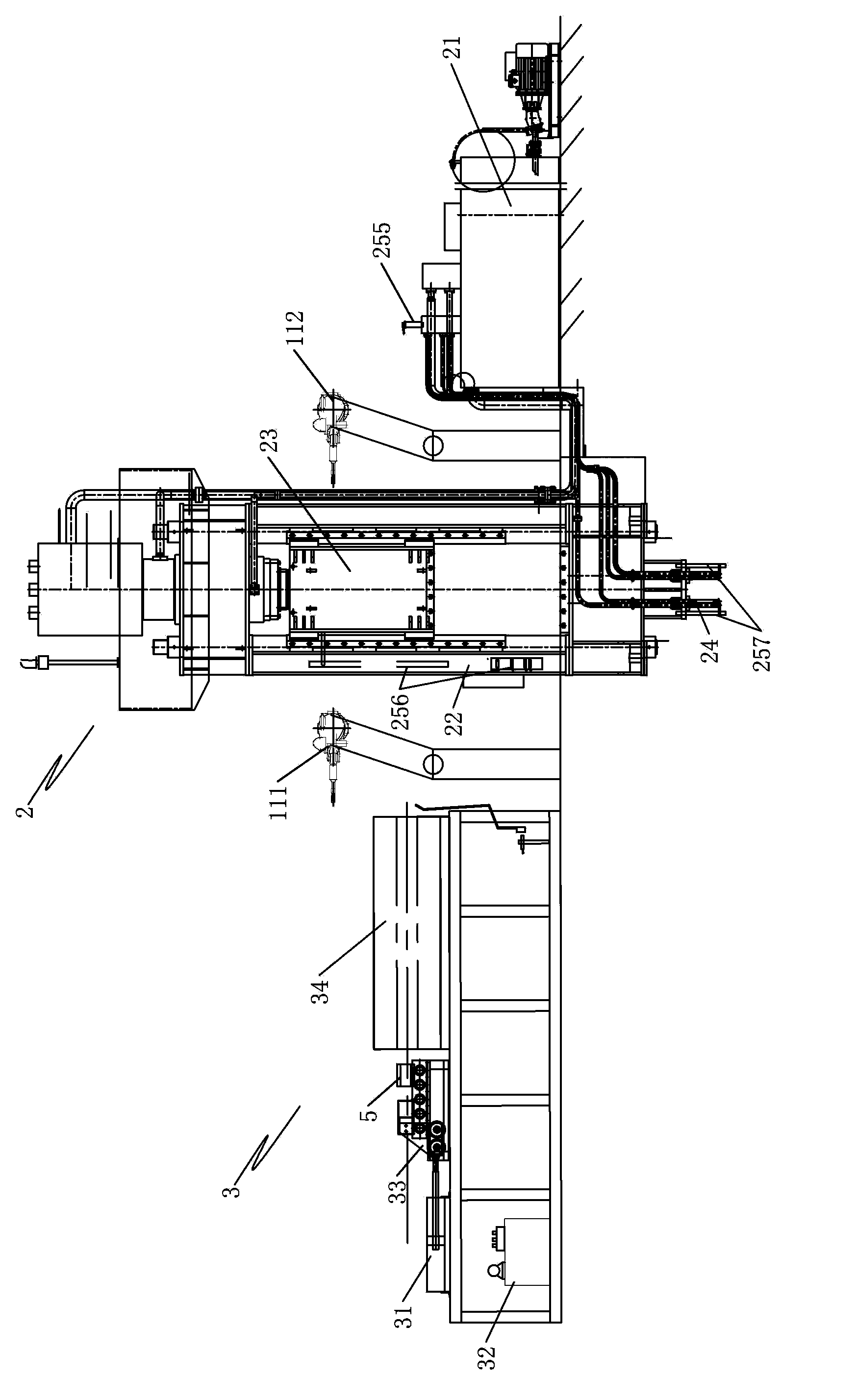
[0034] Such as Figures 1 to 5 As shown, the shaft head extrusion molding system of the present invention includes a hydraulic press 2, an intermediate frequency heating furnace 3 and a robot 1 for handling.

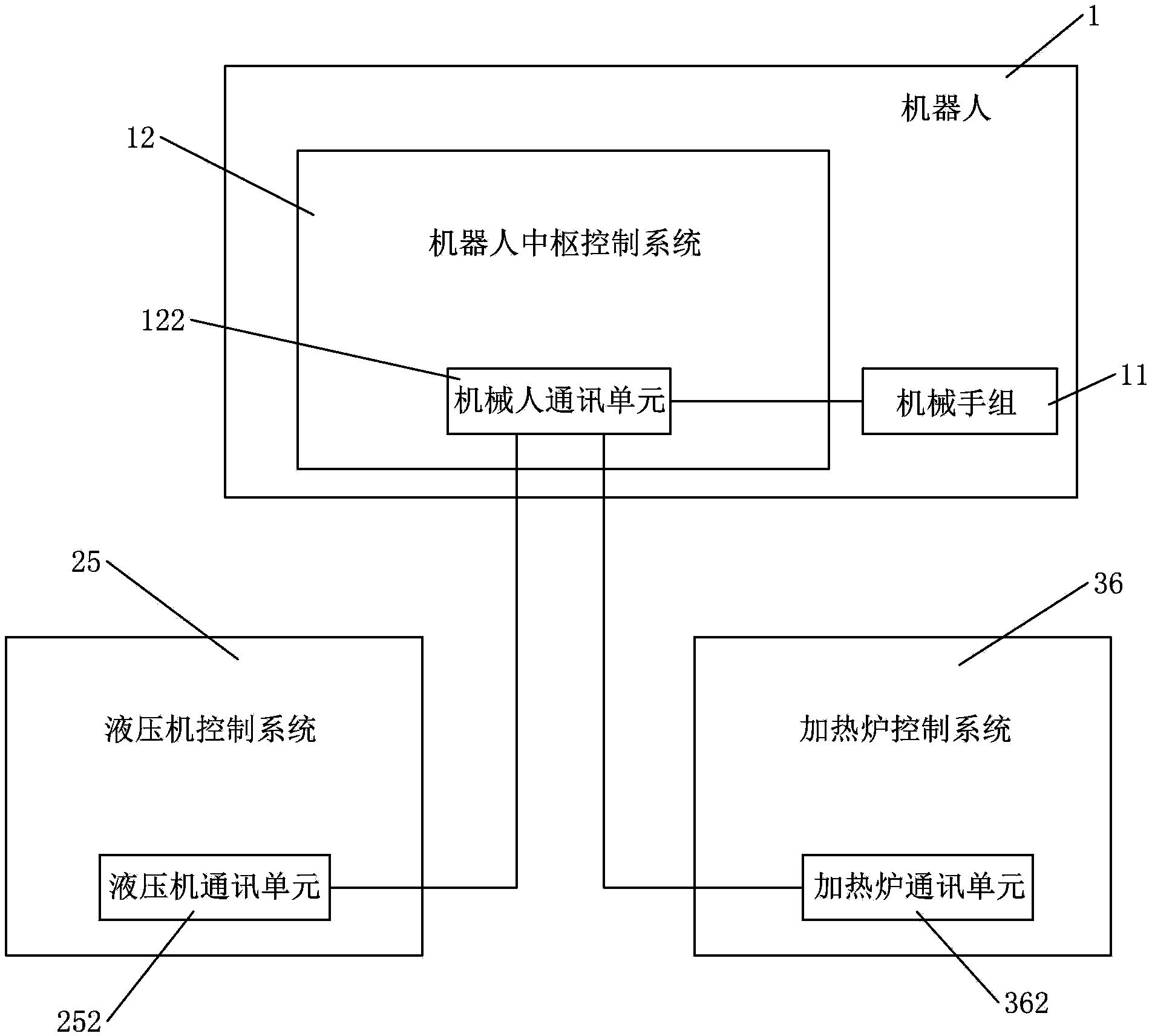
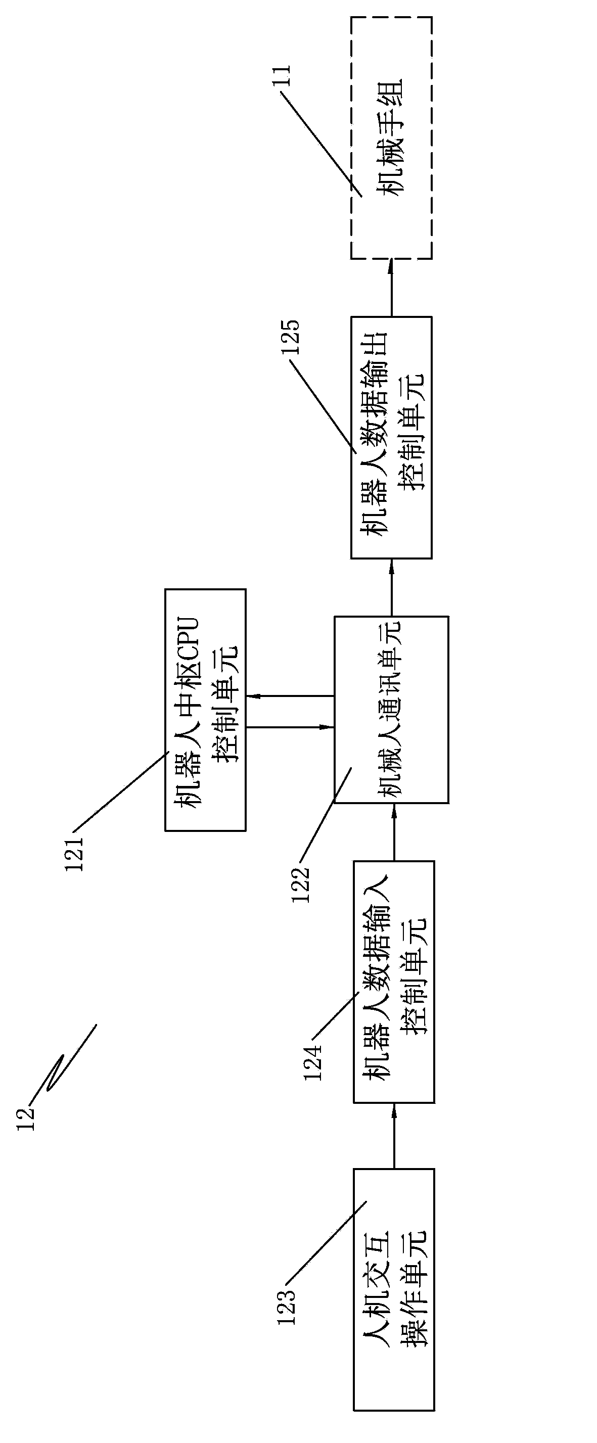
[0035] Such as figure 1 and 3 As shown, the robot 1 includes a robot hand group 11 and a robot control system 12; the robot control system 12 includes a robot central CPU control unit 121, a robot communication unit 122, a human-computer interaction operation unit 123, and a robot data input control unit 124 And the robot data output control unit 125. Specifically: the robot central CPU control unit 121, the robot data input control unit 124 and the robot data output control unit 125 are all electrically connected to the robot communication unit 122, and the human-computer interaction operation unit 123 is connected to the robot data input control unit 124. Electrically connected, the robot arm group 11 is electrically connected to the robot data output control unit ...


PUM


Abstract

The invention discloses a shaft head extrusion forming system and method. The shaft head extrusion forming system comprises a hydraulic machine, an intermediate frequency heating furnace and a robot used for carrying, wherein a center CPU (Central Processing Unit) control unit of the robot receives information data from a man-machine interaction operation unit, a hydraulic machine control system and a heating furnace control system through a robot communication unit, and sends cooperation execution information to a robot hand group, the hydraulic machine control system and the heating furnace control system to perform a cooperation matching work after the information data is treated. A shaft head is extruded by adopting a hollow rod material of the shaft head extrusion forming system. By adopting automatic networking control, the shaft head extrusion forming system is energy-saving and emission-reducing, intelligent and efficient; meanwhile, a hollow rod material is integrally extruded and formed, the heating time is short, and the required pressing force is lower than that of a solid rod material, the hollow rod material can be pressed and formed once, thus the adverse effect of an oxidization skin is prevented, and the product quality is greatly improved.

Description

technical field [0001] The invention relates to a shaft head extrusion molding system, in particular to an intelligent and energy-saving shaft head extrusion molding system. [0002] The present invention also relates to a method of producing a pin using the above pin extrusion system. Background technique [0003] Shaft head 4 (such as Figure 6 shown) is mainly used for the wheel side support at both ends of the axle of the truck such as the trailer. During the operation of the trailer, it not only bears the weight of the entire body and the cargo on board, but also bears a variety of complex alternating stresses due to changes in road conditions. The quality of a class of safety components is of great significance to ensure the safety of vehicles and improve economic benefits. The existing technology used for the axle head is to use solid bar stock, which is reamed and upset on the hydraulic press after local heating in the intermediate frequency heating furnace. The di...

Claims


Application Information

Patent Timeline
IPC IPC(8): B21C23/21B21C29/00B21C31/00B21C33/00
Inventor 王元忠唐公平
Owner GUANGDONG FUWA HEAVY IND
Learn More