Steel tube welding shielding gas storage structure

A technology for storing structure and shielding gas, applied in welding accessories, welding equipment, welding equipment, etc., can solve the problems of de-welding of steel pipe 3 welds, reducing the strength of steel pipe 3, reducing the total amount of shielding gas, etc., to prevent escape, The effect of increasing the contact area

Inactive Publication Date: 2014-06-04
CHENGDU ZHENZHONG ELECTRIC
View PDF6 Cites 0 Cited by
  • Summary
  • Abstract
  • Description
  • Claims
  • Application Information

AI Technical Summary

Problems solved by technology

However, in the semi-sealed mechanism 2, when the shielding gas overflows from the weld seam 4, it will quickly diffuse above the semi-sealed mechanism 2, thereby causing the total amount of shielding gas at the welding

Method used


Image

  • Steel tube welding shielding gas storage structure
  • Steel tube welding shielding gas storage structure
  • Steel tube welding shielding gas storage structure

Examples


Embodiment 1

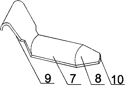
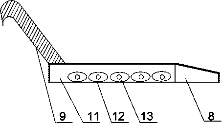
[0023] Such as Figure 1 to Figure 4 As shown, the steel pipe welding shielding gas storage structure of the present invention includes an arc-shaped main body 7, a storage chamber 11 is provided in the arc-shaped main body 7, and one end of the arc-shaped main body 7 is connected with an outlet cavity 8 and the arc main body 7 The other end is connected with a hanging plate 9, which is connected to the external semi-sealed mechanism 2 through a cross bar 6 during operation. The end of the air outlet cavity 8 is provided with an air hole 10, and the air outlet cavity 8 is tapered. It includes rollers 12, which are arranged obliquely on the inner walls of both sides of the storage chamber 11. When the present invention is working, the arc-shaped main body 7 is connected to the external semi-sealed mechanism 2 by the hanging plate 9 through the cross bar 6 to ensure the present invention Stable support is obtained; the shielding gas introduced from the core rod enters the storage...

Embodiment 2

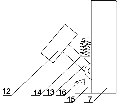
[0025] As shown in the figure, this embodiment is based on embodiment 1, the main shaft 13 of the roller 12 is hinged to the inner wall of the storage chamber 11, and a spring 14 is installed in the middle of the main shaft. The inner wall is connected; it also includes a limit mechanism installed directly below the hinge joint between the main shaft 13 of the roller 12 and the inner wall of the storage chamber 11; the limit mechanism includes a support plate 15 which is provided On the inner wall of the storage chamber 11 and below the main shaft 13 of the roller 12, a protrusion 16 is installed on the support plate 15. The upper surface of the protrusion 16 is an inclined surface; the inclination angle of the inclined surface is 35° ~50°. When welding the steel pipe 3 with a smaller pipe diameter, the inclination angle of the main shaft 13 of the roller 12 is reduced, and the roller 12 is easily in contact with the inner wall of the storage chamber 11, which affects the rotat...


PUM

PropertyMeasurementUnit
Slopeaaaaaaaaaa

Abstract

The invention discloses a steel tube welding shielding gas storage structure. The steel tube welding shielding gas storage structure comprises an arc-shaped body, a storage cavity is formed in the arc-shaped body, one end of the arc-shaped body is connected with a gas outlet cavity, the other end of the arc-shaped body is connected with a hanging plate, in the working process, the hanging plate is connected with an external semi-sealing mechanism through a cross rod, a gas hole is formed in the end of the gas outlet cavity, the gas outlet cavity is conical, and the steel tube welding shielding gas storage structure further comprises idler wheels which are obliquely arranged on the inner walls of the two sides of the storage cavity. Shielding gas fed into a core rod enters the storage cavity, when the shielding gas is accumulated to reach certain degree quantity, the shielding gas enters the gas outlet cavity from the storage cavity, due to the fact that the gas outlet cavity is conical and the gas hole formed in the end of the gas outlet cavity is right opposite to the contact point between a welding head and a welding joint, it can be guaranteed that the shielding gas is ejected from the gas hole at a certain flow rate, and the contact area between the shielding gas and the contact point is enlarged within unit time.

Description

Technical field [0001] The invention relates to an argon arc welding machine, in particular to a steel pipe welding shielding gas storage structure. Background technique [0002] Stainless steel welded pipe requires deep penetration, no oxide inclusions, and the heat affected zone is as small as possible. Tungsten inert gas shielded argon arc welding has good adaptability, high welding quality and good penetration performance. Its products are used in the chemical industry. , Nuclear industry and food industry are widely used. The low welding speed is the shortcoming of argon arc welding. In order to increase the welding speed, foreign research and development have developed a variety of methods. Among them, the single electrode single welding torch is developed and the welding method adopting multiple electrodes and multiple torches is applied in production. Generally, argon arc welding with a three-electrode welding torch is used. The welded steel pipe has a wall thickness of...

Claims


Application Information

Patent Timeline
IPC IPC(8): B23K37/00
CPCB23K9/323B23K9/16
Inventor 陈怀之王刚聂海涛张仁友胡国波
Owner CHENGDU ZHENZHONG ELECTRIC
Why Eureka
Try Eureka