Silicon substrate micro-channel heat exchanger with electric fluid power micro-pump and manufacturing method thereof

A micro-channel heat exchanger and electro-fluid technology, which is applied in the manufacture of semiconductor/solid-state devices, electric solid-state devices, semiconductor devices, etc., can solve the problems of incompatibility in the field of microelectronics heat dissipation, poor flow control accuracy, and large volume. To achieve the effect of stable flow, reliable operation and accurate flow control

Active Publication Date: 2014-06-04
SOUTH CHINA UNIV OF TECH
View PDF7 Cites 23 Cited by
  • Summary
  • Abstract
  • Description
  • Claims
  • Application Information

AI Technical Summary

Problems solved by technology

[0004] However, traditional pumps connected with microchannel heat exchangers have the disadvantages of large volume, high power consumption, high noise, and poor flow control accuracy, which shows serious incompatibility in the field of microelectronic heat dissipation.

Method used


Image

  • Silicon substrate micro-channel heat exchanger with electric fluid power micro-pump and manufacturing method thereof
  • Silicon substrate micro-channel heat exchanger with electric fluid power micro-pump and manufacturing method thereof
  • Silicon substrate micro-channel heat exchanger with electric fluid power micro-pump and manufacturing method thereof

Examples


Embodiment 1

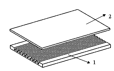
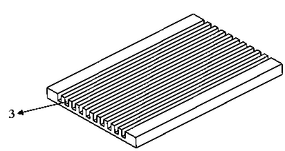
[0035] Such as Figure 1-3 As shown, a silicon-based microchannel heat exchanger with an electrohydrodynamic micropump includes a top plate 2 and a silicon substrate 1 that are closely fitted up and down. The bottom surface of the top plate 2 has the same shape and size as that of the silicon substrate 1. The silicon substrate 1 The upper surface is etched along the length direction with micro-grooves 3 through the reactive ion etching method, and the hydraulic diameter of the micro-grooves 3 is 10um~3mm;

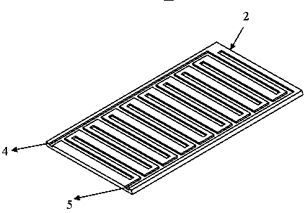
[0036] The top plate 2 is made of aluminum nitride, and the side of the top plate 2 facing the silicon substrate 1 is processed with an electrofluidic power micropump. The electrofluidic power micropump includes an emitter groove 4 and a collector groove processed with a comb-shaped structure. Groove 5, the depth of the emitter groove 4 and the collector groove 5 is 20-40μm, the emitter groove 4 and the collector groove 5 are arranged in parallel and staggered, and the grooves...

Embodiment 2

[0040] The manufacturing method of silicon-based microchannel heat exchanger with electrohydrodynamic micropump includes the steps:

[0041] (1) The emitter trench 4 and the collector trench 5 are processed on the top plate 2 respectively, and the through micro trench 3 is etched along the length direction by the reactive ion etching method on the silicon substrate 1. The top plate 2 uses laser Engraving technology, engraving the comb-tooth-shaped emitter groove 4 and collector groove 5 on the aluminum nitride top plate 2 and removing the burrs and corners on the edge of the groove;

[0042] (2) Using gold immersion treatment or ion sputtering process, the emitter trench 4 and the collector trench 5 in step 1 are plated with gold to prepare the emitter and collector;

[0043] (3) Using an evaporation process, the surface of the top plate after the step (2) is coated with a layer of aluminum nitride film with a thickness of 0.5um~2um;

[0044] (4) The processed top plate 2 and the sili...


PUM

PropertyMeasurementUnit
depthaaaaaaaaaa
widthaaaaaaaaaa

Abstract

The invention discloses a silicon substrate micro-channel heat exchanger with an electric fluid power micro-pump and a manufacturing method thereof. The silicon substrate micro-channel heat exchanger is formed by sealing a silicon substrate and a top aluminum nitride plate with the electric fluid power micro-pump in a bonding mode. A micro-channel is etched in the surface of the silicon substrate according to the reaction ion etching method so that a flow channel for cooling liquid acetone and a place for heat exchanging can be formed. The electric fluid power micro-pump of the top aluminum nitride plate is manufactured through the laser engraving and gold immersing process or the ion sputtering and evaporating process. The electric fluid power micro-pump has the advantages of being stable in flowing, reliable in operation, accurate in flow control, low in energy consumption and the like, and can be effectively integrated with the silicon substrate micro-channel, and therefore the limited space in a micro-electronics element can be effectively saved, and the silicon substrate micro-channel heat exchanger has the wide application prospect in the micro-electronics heat dissipation field.

Description

Technical field [0001] The invention relates to a silicon-based microchannel heat exchanger applied to heat dissipation of microelectronic devices and a manufacturing method thereof, in particular to a silicon-based microchannel heat exchanger with an electrohydrodynamic micropump and a manufacturing method thereof. Background technique [0002] At present, with the rapid progress of microelectronics technology, on the one hand, the feature size of electronic components is as small as possible, and it has developed from the micron level to the sub-micron level. On the other hand, the integration level of the device has been increasing every year since 1959. The high-speed increase of 40%~50% directly leads to the continuous increase of the power consumption of electronic components and the significant increase of heat flux per unit area. At present, the heat dissipation power of high heat flow devices has reached W / m2, and the heat dissipation of next-generation electronic compo...

Claims


Application Information

Patent Timeline
Patent Type & Authority Applications(China)
IPC IPC(8): H01L23/473H01L23/36H01L21/48
Inventor 万珍平周波温万昱闫志国张华杰谭振豪李耀超
Owner SOUTH CHINA UNIV OF TECH
Why Eureka
Try Eureka