
Three-phase controllable polar direct-current electric arc furnace power supply device

A technology of DC electric arc furnace and power supply device, which is applied in the direction of output power conversion device, climate sustainability, high-efficiency power electronic conversion, etc. It can solve the problems of shortened smelting time, easy damage of furnace wall, increased thermal shutdown, etc., and achieves And the effect of convenient operation, novel and reasonable design, and reduced loss of short network

Active Publication Date: 2014-06-04
高辉
View PDF3 Cites 8 Cited by
  • Summary
  • Abstract
  • Description
  • Claims
  • Application Information

AI Technical Summary

Problems solved by technology

[0002] The widely used three-phase AC electric arc furnace had short network length, large voltage drop, large current impact, low transformer power factor, high harmonics, high-voltage switch trip due to short circuit caused by large slump, low production efficiency, and high consumption indicators
In the subsequent technical improvement, the single-phase DC arc furnace was adopted. Although it overcomes the shortcomings of the AC arc furnace, the melting speed is fast and the efficiency is high. Refer to the introduction in the book "DC Electric Arc Furnace Steelmaking Technology", single-phase DC arc furnace Compared with the AC electric arc furnace, the electrode consumption is reduced by 53%, the power consumption is reduced by 5% to 10%, the refractory material is reduced by 30%, and the smelting time is shortened by 5% to 10%. The bottom electrode is often easily damaged, and in the later stage of smelting, a single polarity (the same positive and negative electrodes) causes a single ion in the furnace, which makes the temperature rise slowly in the later stage of smelting, and some complicated measures have to be taken in the process to overcome this problem.
In order to overcome the shortcomings of the single-phase DC electric arc furnace, a DC electric arc furnace with three electrodes with fixed polarity came into being. This device is a power supply device in which one electrode is the cathode and the other is the anode. Although the DC electric arc furnace overcomes some shortcomings of the single electrode plus bottom electrode DC electric arc furnace, because the current of the cathode electrode is the sum of the two anode electrodes, the temperature of the cathode electrode area is high, and the temperature of the two anode electrodes is biased. The disadvantage of low, because there is no arc between the two anode electrodes, it is easy to produce a cold zone, which is not conducive to the uniform melting of the whole charge, so it is necessary to increase the oxygen blowing to melt the cold charge. If the oxygen blowing control is not good, it is easy to cause a large slump Broken electrodes, resulting in increased thermal shutdown
In addition, due to the relatively high temperature in the cathode electrode area, the furnace wall in this area is more likely to be damaged than in other areas, which has an impact on the life of the furnace body

Method used


Image

  • Three-phase controllable polar direct-current electric arc furnace power supply device
  • Three-phase controllable polar direct-current electric arc furnace power supply device
  • Three-phase controllable polar direct-current electric arc furnace power supply device

Examples


Embodiment Construction

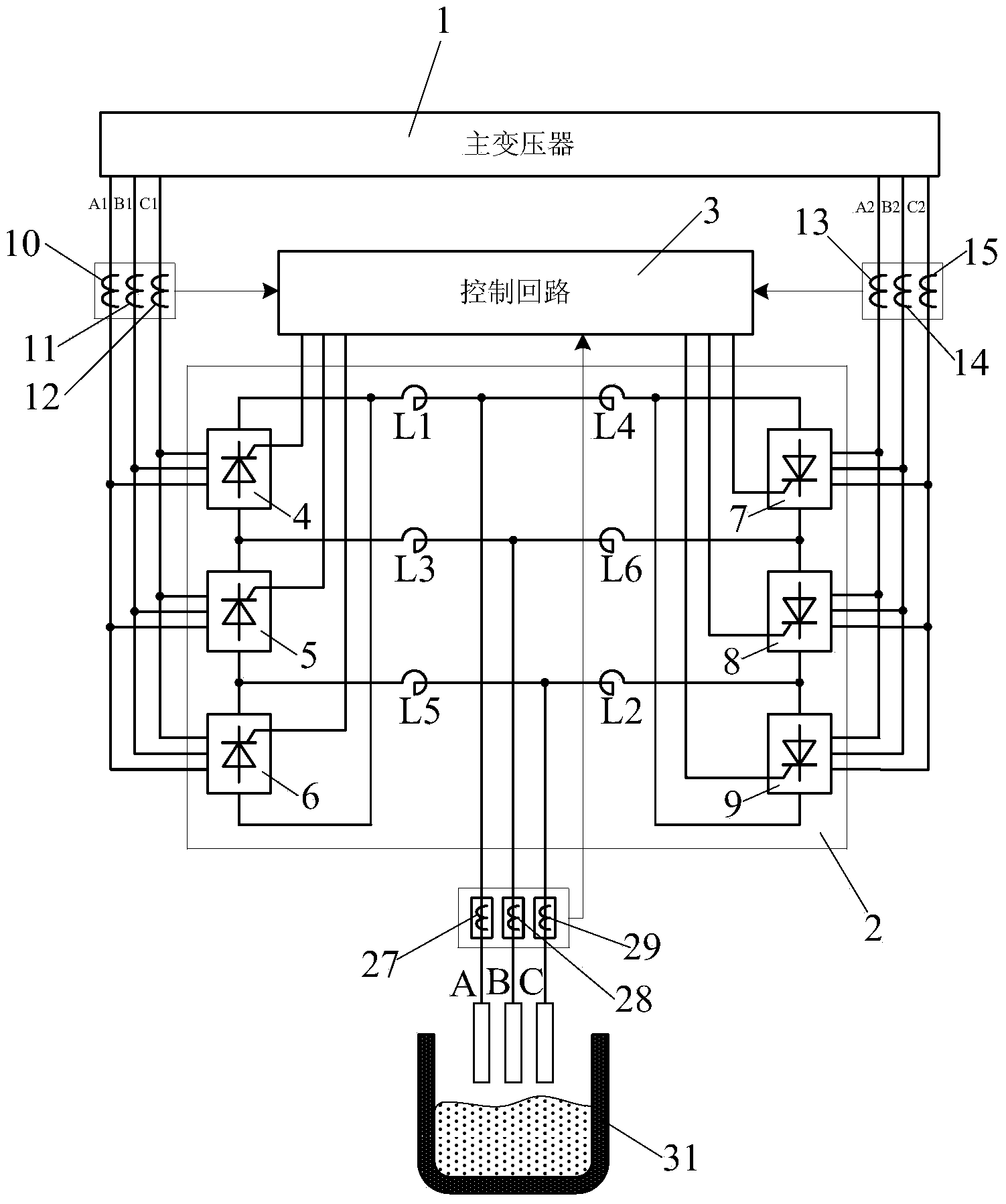
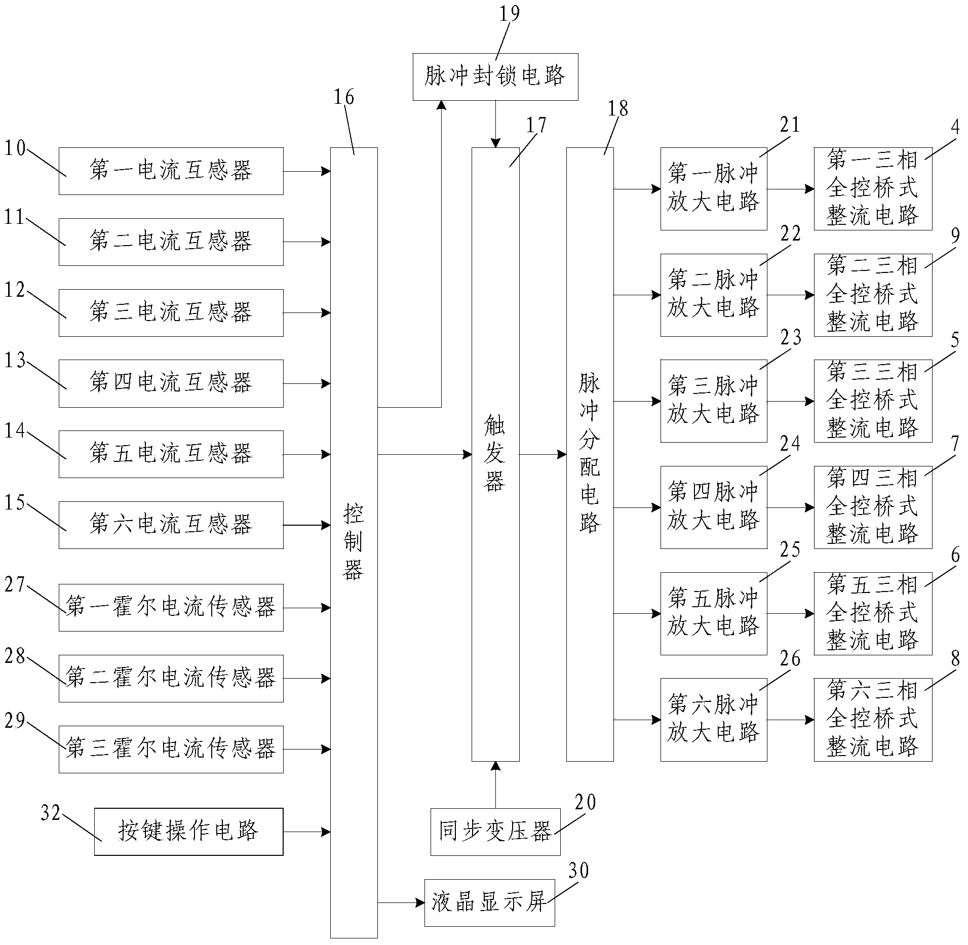
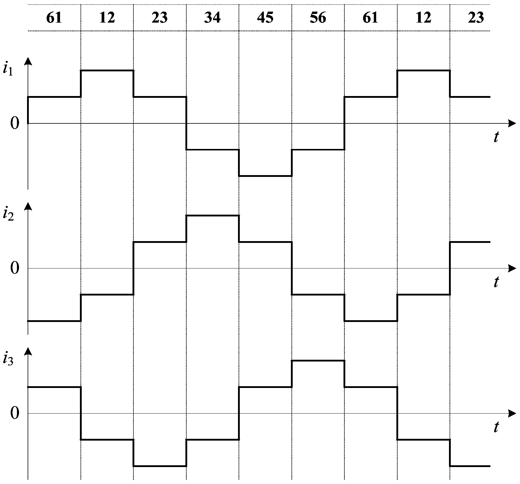
[0039] Such as figure 1 , figure 2 and image 3 As shown, the present invention includes a main transformer 1, a main circuit 2 and a control circuit 3 for controlling the main circuit 2, the secondary side winding of the main transformer 1 is composed of a first winding and a second winding, and the main Loop 2 comprises the first three-phase fully-controlled bridge rectifier circuit 4 connected with the first winding, the third three-phase fully-controlled bridge rectifier circuit 5 and the fifth three-phase fully-controlled bridge rectifier circuit 6, and the second The second three-phase fully-controlled bridge rectifier circuit 9, the fourth three-phase fully-controlled bridge rectifier circuit 7, and the sixth three-phase fully-controlled bridge rectifier circuit 8 connected by windings; the first three-phase fully-controlled bridge rectifier circuit The output end of the rectifier circuit 4 is connected to the input end of the fifth three-phase fully-controlled bridg...


PUM


Abstract

The invention discloses a three-phase controllable polar direct-current electric arc furnace power supply device which comprises a main transformer, a main loop and a control loop. Secondary side windings of the main transformer comprise a first winding and a second winding. The main loop comprises a first three-phase fully-controlled bridge rectifier circuit, a third three-phase fully-controlled bridge rectifier circuit, a fifth three-phase fully-controlled bridge rectifier circuit, a second three-phase fully-controlled bridge rectifier circuit, a fourth three-phase fully-controlled bridge rectifier circuit and a sixth three-phase fully-controlled bridge rectifier circuit, wherein the first three-phase fully-controlled bridge rectifier circuit, the third three-phase fully-controlled bridge rectifier circuit and the fifth three-phase fully-controlled bridge rectifier circuit are connected with the first winding, and the second three-phase fully-controlled bridge rectifier circuit, the fourth three-phase fully-controlled bridge rectifier circuit and the sixth three-phase fully-controlled bridge rectifier circuit are connected with the second winding. The control loop comprises six current transformers, a trigger, a pulse distribution circuit, a pulse inhibition circuit, a synchronous transformer and six pulse amplifying circuits. The three-phase controllable polar direct-current electric arc furnace power supply device is simple in structure, convenient to use and operate and capable of accelerating the melting speed of a direct-current electric arc furnace, reduces heat shut-down, improves heat efficiency, prolongs the service life of a furnace body of the direct-current electric arc furnace, and is high in practicability and convenient to popularize and use.

Description

technical field [0001] The invention belongs to the technical field of electric arc furnace power supply, and in particular relates to a three-phase DC electric arc furnace power supply device with controllable polarity. Background technique [0002] The widely used three-phase AC electric arc furnace had short network length, large voltage drop, large current impact, low transformer power factor, high harmonics, high-voltage switch trip due to short circuit caused by large slump, low production efficiency, and high consumption indicators . In the subsequent technical improvement, the single-phase DC arc furnace was adopted. Although it overcomes the shortcomings of the AC arc furnace, the melting speed is fast and the efficiency is high. Refer to the introduction in the book "DC Electric Arc Furnace Steelmaking Technology", single-phase DC arc furnace Compared with the AC electric arc furnace, the electrode consumption is reduced by 53%, the power consumption is reduced by...

Claims


Application Information

Patent Timeline
Patent Type & Authority Applications(China)
IPC IPC(8): H02M7/162H02M1/42
CPCY02B70/10
Inventor 高辉刘惠民何波马忠义张立军宋双
Owner 高辉
Learn More